 The humble Ethernet cable: key to the future of digital audio?
Already dominant elsewhere, audio over IP is poised to take over the studio world. We explain how it works — and why there are so many protocols!
Today, anyone wishing to add a high-quality, low-latency, multi-channel audio interface to a computer is spoiled for choice, with devices available in a whole host of formats: PCI, PCI Express, Cardbus, Expresscard, FireWire 400 and 800, USB Full-Speed, High-Speed and Super-Speed and Thunderbolt 1 and 2. Until recently, however, the oldest and most ubiquitous connection format of all was absent from this list. It wasn’t until 2011 — 26 years after the publication of the IEEE 802.3 standard — that the first DAW-focused Ethernet recording interfaces appeared. Yet, in principle, Ethernet has unique advantages over other formats, and it has already come to dominate the worlds of installation and high-end live sound.
So why has it taken so long for Ethernet to reach the recording studio, and what key benefits does it have to offer? To find the answers, we need to take a look at the development of Ethernet itself, and that means going back, back through the swirling mists of time...
Into The Ether
 The home of Ethernet: Xerox’s Palo Alto Research Center.Photo: PARCIt’s May, 1973. In Britain, VAT and the Austin Allegro have recently been introduced. In America, Skylab is launched, and Richard Nixon confesses to his role in the Watergate cover-up. Meanwhile, at Xerox’s Palo Alto Research Centre (PARC) in California, a 27-year-old recent PhD graduate called Robert Metcalfe has been tasked with adding networking functionality to the company’s new Alto computer — the machine whose revolutionary graphical user interface would famously ‘inspire’ Steve Jobs. Metcalfe delivers a memo to his employers in which he coins the term ‘ethernet’, and outlines the essentials of what will become the world’s pre-eminent local area networking technology.
 Bob Metcalfe's 1973 sketch of his original 'Ethernet' vision.Photo: PARC
The protocol which Metcalfe described in his memo is now known as Carrier Sense Multiple Access with Collision Detection, or CSMA/CD, after the title of the first IEEE 802.3 standard. The context in which CSMA/CD operates is that of a fully distributed, packet-switched network consisting of autonomous nodes connected to a shared transmission medium (see Figure 1). The autonomy of the nodes means that any given device is free to transmit at any time, while the sharing of a common medium — originally a single coaxial cable — means that if two (or more) nodes decide to begin transmitting at the same time, those transmissions will collide. Since collisions effectively randomise the electrical state of the wire, all such transmissions are void. The only recourse is to try again (which again entails the risk of failure). Clearly this state of affairs has serious implications for the efficiency of a network.
 Figure 1: A shared-medium network.
CSMA/CD seeks to mitigate the problem in two ways. Firstly, all nodes continuously monitor the transmission medium for the presence of a signal (carrier), and will only attempt to send data when none is detected. That’s the ‘carrier sense’ part of the protocol. Carrier sensing alone, however, provides only a statistical defence against collisions, the reason being that signals take time to propagate throughout the network. The fact that a node doesn’t detect a carrier doesn’t mean that another node has not begun transmitting, merely that said transmission has not reached the first node yet. So while carrier sensing reduces the likelihood of collisions, it doesn’t eliminate them, and this is where the second part of the protocol comes in. When any node in the process of transmitting data detects a collision, it stops transmitting that data and instead sends a predefined jamming signal. The duration of the jamming signal is such that it is guaranteed to propagate throughout the entire network, and thus be received by every node. Upon detecting the jamming signal, each node will ‘back off’ for a random period before making any further attempt to transmit. In effect, the network is ‘reset’ as a means of quickly recovering from a collision. The randomisation — Metcalfe’s key insight — mitigates against a ‘repeat’ of the same collision.
A LAN Before Time
Naturally, the description above omits or skates over many technical and historical details for the sake of brevity, but hopefully it provides a clear enough picture of the original Ethernet protocol to make one thing apparent: It was fundamentally unsuited to the job of transporting high-performance audio. However, while CSMA/CD may have been inimical to real-time applications, some found the underlying infrastructure of Ethernet too attractive to ignore — particularly as prices fell and capabilities increased — and a number of companies adopted Ethernet as a vehicle for their own proprietary audio networking protocols.
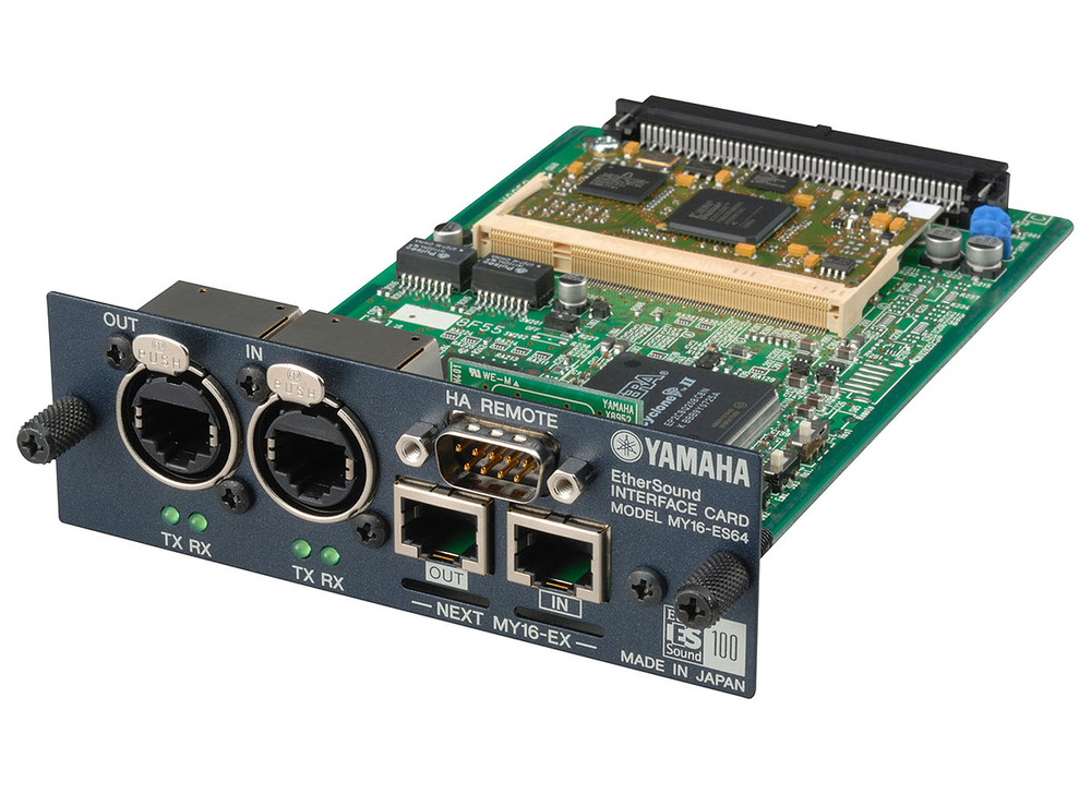
 and EtherSound, as implemented here in expansion cards for Tascam and Yamaha digital mixers.") The first commercially viable audio-over-Ethernet systems were CobraNet (above) and EtherSound, as implemented here in expansion cards for Tascam and Yamaha digital mixers.The first of these Audio over Ethernet (AoE) systems, as they came to be known, was CobraNet, developed in the mid ’90s by a small Colorado company called Peak Audio, and later acquired by chip makers Cirrus Logic. CobraNet works by designating one device on the network as the ‘conductor’, while the remaining devices are known as ‘performers’. Every 750 s, the conductor transmits a beat packet which is received by all of the performers. The beat packet provides the timing for the network, and also contains an ordered permission list, which tells each performer when, during the cycle, to transmit its data, thereby avoiding the problem of collisions. (CobraNet’s arbitration scheme is very similar to FireWire’s isochronous mode.)
The first commercially viable audio-over-Ethernet systems were CobraNet (above) and EtherSound, as implemented here in expansion cards for Tascam and Yamaha digital mixers.The first of these Audio over Ethernet (AoE) systems, as they came to be known, was CobraNet, developed in the mid ’90s by a small Colorado company called Peak Audio, and later acquired by chip makers Cirrus Logic. CobraNet works by designating one device on the network as the ‘conductor’, while the remaining devices are known as ‘performers’. Every 750 s, the conductor transmits a beat packet which is received by all of the performers. The beat packet provides the timing for the network, and also contains an ordered permission list, which tells each performer when, during the cycle, to transmit its data, thereby avoiding the problem of collisions. (CobraNet’s arbitration scheme is very similar to FireWire’s isochronous mode.)
 In 2001, French company Digigram brought to market a rival system called EtherSound. Unlike CobraNet, EtherSound relied upon Ethernet’s newly introduced full-duplex capabilities (discussed below) to provide bi-directional audio transport. All EtherSound devices have two network ports — In and Out — and are connected in a daisy-chain topology. At one end of the chain is a designated primary master, which is the originating source of EtherSound frames (packets). Each frame has space for one sample per audio channel (of which there can be up to 64 at standard sampling rates), hence the frame rate is equivalent to the audio sample rate, and acts as the clock source for the network. Samples may be inserted into or extracted from the packet as it passes downstream through each device in the chain. A designated loopback device returns the packet to the primary master, which then makes any channel inserted into the original downstream flow available to devices upstream of the loopback device.
The principal markets for CobraNet and EtherSound were large installations: conference centres, sporting venues, transport terminals, theme parks, and anywhere else where audio needed to be widely distributed. The first deployment of CobraNet, for example, was to provide background music at Disney’s Animal Kingdom theme park. Both CobraNet and EtherSound had high price tags, and the former in particular had a reputation for being difficult to configure. Since both derived their timing from packet transmission, end-point devices required sophisticated phase-locked loops to filter jitter, and neither could maintain phase coherence without the use of a separate word clock network. Finally, both were ultimately locked in by the undeniably clever solutions they’d developed to overcome the shortcomings of Ethernet as it existed at the time of their development, and were thus unable to evolve to fully take advantage of subsequent advances in the technology.
When Is A Network Not A Network?
While thousands of CobraNet and EtherSound networks are still in use worldwide, you may have noticed that the previous paragraph discussed them in the past tense. That’s because both have seen their market share steadily eroded by Dante (chiefly), and both are now considered obsolete for new installations. At the same time, the technological advances referred to above have been exploited by a growing number of audio manufacturers to implement their own, far simpler, audio transport mechanisms on top of Ethernet.
These systems fall into two basic categories, usually characterised as ‘layer 1’ and ‘layer 2’ systems; however, these designations are somewhat misleading, because they imply a more fundamental distinction than really exists. A more accurate categorisation might be: Those that include MAC headers (but don’t really use them, at least not in the conventional sense) and those that don’t.
The latter category is exemplified by SuperMAC, developed by Sony Oxford around the turn of the century. SuperMAC was standardised as AES50 in 2005, and the rights were acquired by Klark Teknik in 2007. The eight wires in the standard Ethernet cable are treated by AES50 as four differential pairs: two for bi-directional data, as per standard 100Mb/s Ethernet, and two for bi-directional word clock.
AES50 only supports 100Mb/s Ethernet, and without the protocol header requirement, this essentially makes it a clear, 12.5MB/s bi-directional channel, on which (almost) raw sample data is transmitted. In addition to the Ethernet physical layer framing, AES50 interleaves a small amount of error-correction metadata too, and also reserves a 0.625MB/s Ethernet/IP channel for out-of-band communication. After these overheads, the 12.5MB/s data rate is good for 48 (fixed) channels in each direction at 48kHz, or half that at 96kHz; these are the only sample rates supported by AES50, which is aimed squarely at pro audio applications.
However, what you’ve got with SuperMAC/AES50 is an Ethernet-based point-to-point interface rather than a network, since no MAC header means no addressing, and that means no switching. Standard Ethernet switches would have no idea what to do with the bizarre and alien stream of data that raw audio samples in layer 1 frames would represent to them. Proprietary ‘matrix routers’ are available, but the name itself gives the game away: You can send anything anywhere, but not at any time. In other words, any device can stream to any other device, but only if a third device isn’t already doing so. A routed AES50 system is logically an ‘either/or’ switching matrix rather than an ‘anything-anywhere-anytime’ network.
Up A Layer
AES50’s non-standard use of the Ethernet physical layer means that it can’t run over ordinary network infrastructure, but in more recent times, a number of manufacturer-specific systems have emerged that are able to use off-the-shelf NICs and switches. These include Allen & Heath’s ACE/dSNAKE, Roland’s REAC and Waves/Digico’s SoundGrid. However, although they use Ethernet, and are typically described as ‘layer 2 networks’, in a sense they’re not really networks at all. (My personal definition is functional: Can you send anything anywhere at any time? If not, it isn’t a network.) They’re much more akin to digital audio transports such as AES3 or ADAT, except that they happen to use Ethernet as a medium.
 The Digigrid system from Waves and Digico is a ‘layer 2’ system, meaning that although it can use standard Ethernet hardware such as switches, it requires its own dedicated network infrastructure.Each Ethernet frame carries one sample per channel, interleaved on a per-channel basis, so the packet transmission rate is equal to the sample rate. Like AES50, they’re synchronous transports: they use fixed-length frames (representing x number of audio channel ‘slots’) regardless of how many channels of actual data a frame might contain. An additional channel slot (invariably channel 0) carries a sync byte: if the packet in question is coming from the clock master, this byte provides the sample clock for the network.
Ethernet offers three types of transmission: unicast (one to one), multicast (one to several) and broadcast. The distinctive feature of these systems, and the reason why they are arguably not networks, is that everything is broadcast, meaning everything goes everywhere. Each packet uses the same broadcast destination address in its MAC header, so although the MAC header’s there, it isn’t really being used for packet routing. Instead, packets are dropped, filtered or routed by application software operating above the network. In addition to enabling the broadcast functionality, the presence of a MAC header also allows frames to be forwarded by standard Ethernet switches.
Obviously, any asynchronous (ie. random) traffic would quickly disrupt this sort of synchronous scheme, in rather the same way trying to send an email over MADI would, so these systems require their own dedicated network infrastructure that’s not shared with anything else. Another shortcoming is that the simple clocking mechanism, while effective, is not robust over long distances or multiple switch hops; and, crucially, though you can send anything anywhere, you can’t do it at any time, since the system is logically more like a switched bus, where certain operations or assignments preclude others. Nonetheless, they’re still impressive systems in their own right, and their simplicity has enabled them to take advantage of Ethernet’s relentless technical advance more easily than CobraNet or EtherSound were ultimately able to.
LAN Line
This technical advance proceeded at a great pace during the 1990s. Two developments in particular meant that before that decade was out, standard Ethernet had not only rid itself of contention-based media access control, but had become an extremely fast, flexible and reliable technology to boot.
The first major advance came in 1990, when the publication of IEEE Std 802.1D formalised the concept of bridging. The idea behind bridging is to allow continuity at the data link layer, whilst isolating the physical (electrical) layer. A bridge does this by storing (buffering) data coming in, then forwarding it to the next physical link, in essence creating two isolated collision domains where there used to be one. This is done in hardware, and is extremely fast: even the worst-case delay in traversing a bridge in a heavily loaded network is typically measured in the low tens of microseconds. Expanding the concept, we arrive at the idead of a switch: a multi-port bridge. Rather than being attached to a shared medium, each individual device on the network is instead connected to its own port on a switch, with each port having an associated output queue (packet buffer). Traffic arriving on any port can be forwarded to any other port’s — or ports’ — output queue(s) based on the destination address in the packet header.
 Figure 2: A bridged network with half-duplex links.
What this means is that instead of there being one big collision domain, in which a collision affects the entire network, a switched network is effectively partitioned into multiple individual collision domains which are isolated from one another. The only ‘shared medium’ in a bridged network exists between a single node and its corresponding switch port, and any collision occurring there has no impact on the rest of the network (see Figure 2 above).
So far we’ve been following Ethernet terminology and talking about a ‘shared medium’, but there’s another, more generic term which describes a communication channel which behaves in this way, and that’s ‘half-duplex’. A half-duplex connection is one which permits the transmission of signals in both directions, but not simultaneously. In half-duplex systems with a deterministic medium-access mechanism — such as FireWire 400 or USB 2.0 — this is not a problem, but as we’ve seen, even a bridged Ethernet connection is still prone to collisions (albeit localised to a single link) if a node and the switch port to which it’s attached attempt to transmit simultaneously. The obvious solution to this problem is to make the links between nodes and switches full-duplex, ie. capable of transmitting in both directions simultaneously, and that’s exactly what happened in the late ’90s. The switch to full-duplex links finally eradicated the possibility of collisions on a shared medium network — by dispensing with the shared medium! Now each and every node and switch port in the network had its own dedicated, contention-free transmission and reception channels (Figure 3). The publication of IEEE Std 802.3x in 1997 effectively consigned collisions, shared media and CSMA/CD to history. Almost as an added bonus, the bandwidth of each link was effectively doubled — since the rated transfer rate now became bi-directional — and medium-access latency was reduced to almost nothing.
 Figure 3: A bridged network with full-duplex links.
While switches and full-duplex links were the most fundamental technical developments of the period, they were far from being the only ones. At the same time as bridges were standardised, the transition from bulky, vampire-tapped coaxial to slim, flexible unshielded twisted-pair (UTP) cabling occurred. The decade also saw speeds increase by two orders of magnitude, first to 100Mbits/s in 1995, and then to 1000Mbits/s in 1999. Although CSMA/CD remained in the title of the Ethernet standard for many years, and the functionality remains buried away in the Ethernet MAC (Media Access Controller) for the sake of compliance with the standard, by the end of the ’90s both were already vestiges of the past. Real-world deployment always lags a couple of years behind the publication of standards, but Ethernet around the turn of the century bore little resemblance to Bob Metcalfe’s memo of 1973.
Borrowed Time
It goes without saying that the rapid pace of technological advance would never have been maintained if Ethernet had not simultaneously been enjoying massive commercial success. Ultimately, development goes hand in hand with investment, and investment follows the bottom line. In the course of the ’90s, Ethernet not only saw off its early challengers for the LAN market — IBM’s Token Ring, and the Token Bus system championed by General Motors (who felt that LANs were too important to be left to ‘computer people’) — but also found its ‘killer app’ in the shape of the Internet.
As if to illustrate the principle that success breeds success, the increasing attractiveness of Ethernet at this time led many sectors that had previously relied on specialised networking solutions to begin investigating its possibilities, and ultimately, to become involved in its development. Among them were parts of the scientific instrumentation community, and companies in the industrial automation sector. The participation of these parties led to the publication in 2002 of IEEE Std 1588. This describes a technology called Precision Time Protocol, which enables LAN-wide clock synchronisation to sub-microsecond accuracy (see the ‘How Time Flies’ box). In an example of a phenomenon to which the recording industry perhaps owes its entire existence — developments in one field bringing incidental benefits to another — PTP unintentionally gave a massive boost to the possibility of making standards-based Ethernet a viable medium for high-performance audio and video transport; and, in the early years of the 21st Century, some major players began to take a serious interest in doing just that.
LAN Of Opportunity
 Probably the first guitar to feature a built-in RJ45 socket, Gibson’s HD.6X was designed to take advantage of their MaGIC data-transfer protocol.In 2004, after a year or so of informal discussion, a group of companies including Samsung, NEC, Pioneer, Broadcom, Nortel and Gibson formed the Residential Ethernet Study Group (RESG) under the auspices of the IEEE 802.3 (Ethernet) Working Group. The remit of the RESG, as the name might suggest, was to investigate the possibility of developing an Ethernet specification which would facilitate device interconnection and media streaming within the home. Incidentally, if the involvement of a guitar company seems somewhat incongruous here, it should be noted that Gibson had by this time already developed an audio transport called MaGIC, which used the Ethernet physical layer, and indeed hoped that it would form the basis of the IEEE standard. If nothing else, their presence ensured that the needs of musicians were taken into account from the start: an early RESG tutorial document includes a section written by Gibson’s Alexei Beliaev which discusses scenarios such as “Home recording” and “Garage jam session”.
By the end of 2005, it was clear to the RESG that the most significant obstacle to progress was the non-determinism inherent in packet queuing and forwarding within bridges. However, since bridging frequently occurs not only within but between individual network types — Ethernet and Wi-Fi, for example — it’s dealt with by a stand-alone working group, IEEE 802.1, which has oversight of bridging and architecture for all 802 LAN technologies. As bridging was where the critical work needed to be done, the project therefore moved from the 802.3 (Ethernet) Working Group to the 802.1 Working Group. By now the scope of the endeavour had expanded too, with the growing involvement of companies from fields such as pro audio, broadcasting and commercial sound among others. In 2006 the project was ratified as the AV Bridging Task Group, less formally known as AVB, under the chairmanship of Michael Johas Teener (see the ‘LAN Lord’ box).
It would be almost four years before the labours of the AVB task group began to bear fruit, and almost eight until all of the components of a complete ‘first generation’ AVB specification were in place. This may seem like an extremely long time, but then like most standards bodies, the IEEE is an extremely cautious organisation, and that’s undoubtedly as it should be. A world that increasingly relies on Ethernet won’t tolerate it getting broken just because some damned fool wants to play a guitar through it, so to speak. Perhaps even more significant is the fact that the standards-making process is a highly democratic one, to which each of the participants frequently bring different — and often contradictory — wish-lists for a given standard, all of which have to be haggled over, formalised, drafted, voted upon, reviewed etc. It inevitably takes time. Elsewhere, however, events were moving apace.
A LAN Down Under
Back in 2003, the members of the nascent RESG were not the only people to see the potential of using fast, full-duplex Ethernet for high-performance audio transport. Nearly 10,000 miles away from the IEEE’s New Jersey headquarters, a team of engineers who’d recently found themselves on the sharp end of Motorola’s decision to close their Australian research facility were seeking a new home at NICTA (National ICT Australia), a government-funded centre for IT and communications R&D in Sydney. Led by Aidan Williams, an electronics engineer and computer scientist who also happens to be a keen musician, the team pitched the idea of developing a system that would allow high-quality, low-latency audio streaming over Ethernet using standard TCP/IP protocols (along with a proprietary audio transport protocol, and an implementation of PTP for clock synchronisation). Such was the success of the project that in 2006 it became the first to be spun-out of NICTA as a commercial venture. The new company took the name Audinate, and the technology they’d developed was christened Dante.
 at the recording studio market.") Focusrite’s Dante-based RedNet system is the first Ethernet audio range targeted (in part) at the recording studio market.A little over a decade later, Dante is firmly established as the de facto standard for high-performance AoIP (Audio over Internet Protocol). It wasn’t the first system of its type on the market — that accolade goes to Telos/Axia’s Livewire, introduced in 2003 — or even the second (Wheatnet IP arrived in 2005), and other players have subsequently entered the market, but none have had the impact of Dante. Where Audinate differ from competing developers is partly in the markets they target, but chiefly in their business model. While their rivals are mostly confined to the broadcast sector, Audinate have focused far more on pro-audio and installed sound — the traditional stomping ground of AoE systems such as EtherSound and CobraNet — as well as ‘niche’ markets like studio recording. The alternative AoIP solutions were mainly developed by companies whose core business is producing equipment for the broadcast industry, so each of their respective AoIP implementations is mainly marketed as an ‘added value’ feature of their own products. For Audinate, on the other hand, Dante connectivity is the product.
Focusrite’s Dante-based RedNet system is the first Ethernet audio range targeted (in part) at the recording studio market.A little over a decade later, Dante is firmly established as the de facto standard for high-performance AoIP (Audio over Internet Protocol). It wasn’t the first system of its type on the market — that accolade goes to Telos/Axia’s Livewire, introduced in 2003 — or even the second (Wheatnet IP arrived in 2005), and other players have subsequently entered the market, but none have had the impact of Dante. Where Audinate differ from competing developers is partly in the markets they target, but chiefly in their business model. While their rivals are mostly confined to the broadcast sector, Audinate have focused far more on pro-audio and installed sound — the traditional stomping ground of AoE systems such as EtherSound and CobraNet — as well as ‘niche’ markets like studio recording. The alternative AoIP solutions were mainly developed by companies whose core business is producing equipment for the broadcast industry, so each of their respective AoIP implementations is mainly marketed as an ‘added value’ feature of their own products. For Audinate, on the other hand, Dante connectivity is the product.
 Audinate’s Brooklyn II provides a complete Dante audio interface on a card. Following this paradigm, Audinate supply hardware implementations of Dante under licence to OEMs, who integrate them into their PCB (printed circuit board) designs. From the OEM’s perspective, the simplest option is the Brooklyn II module, which provides a complete 64-channel (bi-directional) FPGA-based Dante interface on a Mini-PCI plug-in card, making integration a simple matter of implementing a standard Mini-PCI header on the host audio device’s main PCB. While Brooklyn II is clearly the mainstream choice, Audinate also offer two discrete ICs (integrated circuits) which respectively cater for the extremes of the capability spectrum. At one end is the 512 x 512-channel(!) Dante HC design, executed on a Xilinx Spartan-6 FPGA, and at the other are the two-in, two-out and four-in, four-out Ultimo chips.
In production volumes, these solutions are supplied as bare ICs, giving the OEMs themselves the task of implementing the kind of support circuitry which the Brooklyn II module provides as standard, and otherwise dealing with the lower-level details of integrating Dante into their circuit designs. Luckily, product development kits (PDKs) are available for all three solutions, which provide both the hardware and software components of a complete reference design, along with the programming tools and documentation required to work with them. The PDK hardware consists of a circuit board which hosts the relevant Dante chip or module in the context of a prototypical ‘complete system’, including Ethernet ports, word clock I/O on BNC connectors, and analogue and digital audio I/O in a variety of standard formats, including co-axial SPDIF and AES3 on XLRs. The PDKs serve as both a framework within which to learn the platform, and as a conceptual starting point for original product development.
Play Your Cards Right
At the other end of the Ethernet cable, as it were, Audinate provide not one but two means of adding Dante connectivity to a computer. The first is a high-performance PCIe card, which is currently available under both the Yamaha and Focusrite brand names. The second is a software-only virtual soundcard (Dante VSC) which uses the host computer’s network stack and built-in Ethernet port to connect to a Dante-enabled network or device. The Dante VSC is commercially available for download from the Audinate web site, and is often bundled with hardware by audio device manufacturers, since it essentially fills the role of an installable device driver when connecting a single device directly to a computer.
 Currently available under both the Focusrite and Yamaha brands, the Dante PCIe card supports up to 128 channels of audio I/O at base sample rates with good low-latency performance.Both the Dante VSC, and device drivers for the PCIe card, are available in Windows and Mac OS X versions. The FPGA-based PCIe card can handle 16, 24 and 32-bit samples, and provides 128 bi-directional audio channels at 44.1kHz/48kHz/88.2/96kHz with it dropping to 64 channels at 176.4/192kHz. The virtual soundcard can manage up to 64 channels at normal sample rates (or 32 and 16 at double and quad rates), though performance is ultimately host-dependent. To run Dante VSC, its also necessary to have at least one Dante hardware device on the network to provide the PTP master clock reference, since software running under a general-purpose operating system such as Windows or OS X simply can’t achieve the required degree of accuracy.
The PCIe card and the VSC both provide ASIO and WDM support under Windows, and Core Audio support in Mac OS X, making them compatible with all modern DAW applications (not to mention the vast majority of audio software generally). From the perspective of applications, they appear as standard audio devices. In terms of raw performance, the PCIe card is unsurprisingly superior to the VSC by a considerable margin. A YouTube video review of the Focusrite RedNet 2 by SOS contributor and Forum regular Robin Vincent, of Molten Music Technology, includes a comparison of its performance when connected to a PC via the PCIe card and by means of Dante VSC. A casual analysis of the latency values reported to Cubase during the video suggests that the Dante PCIe card implements a fixed 32-sample safety buffer on both the input and the output sides, independent of the selected ASIO buffer size, and additionally that the values reported to Cubase don’t include A-D and D-A conversion latencies (though that’s to be expected, since it’s the card itself, not the converter box attached to it, that’s reporting its ASIO latency to the application). These caveats notwithstanding, the low-latency performance of the Dante PCIe card appears to be in a similar league to that of ‘gold standard’ interfaces from the likes of RME, Lynx and MOTU. The Dante VSC doesn’t come close to matching this performance, but it’s nonetheless capable of combined input and output latency values down to around 10ms, which are similar to those typically achieved by mid-range USB 2.0 or FireWire interfaces.
The gap in performance between the PCIe card and the VSC must, of course, be weighed against the fact that the latter costs a fraction of the price of the former. An unlimited Dante VSC licence costs 29.99 Australian dollars from the Audinate web site, which is equivalent to about £18.65 at the time of writing, whereas the original Rednet PCIe card has an MSRP of £799. An obvious benefit of the virtual soundcard is that it provides a simple solution for laptop users wishing to incorporate Dante into their setups (though laptop power users might also be interested to know that Audinate have successfully tested the latest PCIe-R card with a number of Thunderbolt expansion chassis, including the Magma ExpressBox 1T).
Audinate have created an attractive ecosystem for audio manufacturers interested in adding networking capabilities to their products, offering a comprehensive set of hardware and software components which make integrating Dante into an audio device design a fairly straightforward process. Some observers have pointed out that no proprietary interface format has ever succeeded in the long term, and indeed, a glance at those listed in the opening paragraph of this article reveals the long-standing preference for standardised formats. It’s perhaps interesting, though, that said list already includes one potential exception to this rule, namely Thunderbolt, which appears still to be thriving in the sixth year of its commercial existence. Whether Thunderbolt and Dante truly represent the start of a shift in historical trends, or turn out to be stopgap solutions ultimately swept away by cabled PCI Express and AVB, at present both are clearly coming rather than going.
Building Bridges
 AVB’s Class-B mode is designed to be capable of use over Wi-Fi, though low-latency operation is not an option. In 2009, a year after the first Dante-enabled product (the Dolby Lake processor) hit the market, the first of a set of IEEE standards which collectively define AVB was published. By the time the last of these was issued in 2013, Audinate had around 100 licensees, giving Dante a commercial head start over AVB. So what does the new IEEE standard have to offer?
The core AVB functionality consists of three protocols: the Stream Reservation Protocol (SRP), via which Talkers and Listeners negotiate and lock down end-to-end bandwidth for a stream; Forwarding and Queuing Enhancements for Time Sensitive Streams (FQTSS), which both prioritises and regularises audio packet transmission; and the generalised Precision Time Protocol (gPTP), which allows a synchronised reference clock to be maintained at every node on the network. FQTSS and SRP are the protocols that put the ‘bridging’ into Audio Video Bridging, and as such, they’re incorporated into what is now the principal 802.1 bridging document, IEEE 802.1Q, where they’re defined in clauses 34 and 35 respectively. Since it’s regarded as a ‘service’ rather than a core facet of bridge functionality, gPTP gets its own document, IEEE Std 802.1AS-2011. A second stand-alone document, 802.1BA-2011; Audio Video Bridging (AVB) Systems, is basically a ‘glue’ standard, formally mandating the simultaneous use of the three protocols discussed above, as well as specifying the requirements of the wider operating environment, such as the need for full-duplex links at 100Mb/s or better for Class A traffic (see below). Anyone wishing to explore the nuts and bolts of AVB may be interested to know that all 802 standards are downloadable free of charge via the IEEE Get Program (http://standards.ieee.org/about/get/#get802).
 MOTU are among the manufacturers of project-studio equipment who have committed to the AVB protocol.AVB defines two traffic classes: Class A and Class B. Class A specifies an end-to-end latency of 2ms or less over seven network hops, a specification which requires full-duplex 100Mb/s or gigabit Ethernet connections or better for its implementation. Class B, meanwhile, specifies sub-50ms latency over seven hops, allowing up to two of those hops to be over Wi-Fi or CSNs (co-ordinated shared networks — in essence, shared-medium systems, but with explicit arbitration — examples taken from the AVB standards include G.hn and MoCA), which typically have high medium-access latencies (802.11 Wi-Fi is on the order of 20ms, for example). Class B is AVB satisfying both its RESG heritage, by accommodating consumer-friendly technologies, and its 802.1 mandate, by not being Ethernet-specific.
Up Streams
The unit of transmission in an AVB domain is the stream. A stream is produced by a single Talker, and consumed by one or more Listeners. The relationship between streams and traffic classes is based on the notion of a class observation interval (usually just ‘class interval’). The Class A observation interval is 125µs, while Class B’s is 250µs. One packet per stream is typically sent during each class interval, which for Class A equates to a packet rate of 8000 per second. A simple bit of maths shows that this works out to precisely six samples per packet at a sample rate of 48kHz (48000/8000=6), while at 96kHz and 192kHz, each of the 8000 packets will respectively contain 12 and 24 samples per audio channel.
It’s worth clearing up a common misapprehension here. The AVB packet rate, unlike that of EtherSound, for example, is in no way connected to sample clock synchronisation — that’s handled entirely separately by gPTP/AVTP (see below). The packet rate is simply a function of the class interval, and the sole purpose of the class interval is to limit stream bandwidth to no more than that commensurate with the maximum permitted size of a standard VLAN-tagged Ethernet frame, which at 1542 bytes takes 123.36µs to transmit on a 100Mb/s link (the minimum supported by AVB).
Streams based on a sample rate of 44.1kHz or its multiples, which don’t divide evenly into 8000 packets per second, can be handled in one of two ways, known as blocking or non-blocking transmission. In the former case, packets are not sent until six samples (at 44.1kHz) become available (approximately every 136.05µs), which simply means sending 7350 packets per second rather than 8000. In the case of non-blocking transmission, 8000 packets are still sent every second, but the number of samples in each packet varies. At 44.1kHz, for example, the required result is produced by alternating packets containing five samples with packets containing six samples, but substituting every 79th packet with a packet of six samples.
The number of audio channels a stream can contain is determined by the interplay of several factors. Obviously, no stream can exceed the available bandwidth of the link, which by default is limited to 75 percent of the total capacity, meaning 75Mb/s for 100BASE-TX and 750Mb/s for 1000BASE-T. Another limiting factor for a single stream has already been mentioned, and that’s the maximum allowable size of an Ethernet frame, which is 1542 bytes, with a payload of 1500 bytes. The AVTP transport protocol (discussed below) requires a 32 byte header, leaving 1468 free for sample data. Under AVTP, 24-bit samples are encapsulated in 32-bit frames, meaning that six samples occupy 24 bytes. 1468/24 is 61.66, but since you can’t have a fraction of a sample, we can say that 61 channels is the absolute theoretical maximum for a single AVTP stream, independent of network speed. Such a stream will have a transmission rate of just over 96Mbits/s, which is no problem on a gigabit link, but exceeds the 75Mb/s default maximum on a 100BASE-TX link. The per-stream limit in the latter case is 45 channels.
An Orderly Queue
According to the character of Joseph Garcin in Sartre’s No Exit, “hell is other people.” Had Garcin been developing a high-performance audio network, he might instead have come to the conclusion that hell is other traffic. The issue is that on entering a switch, all packets bound for the same onward link (to the next switch, for example), regardless of source or ultimate destination, go into the same output queue on a first come, first served basis. As a result, that queue will contain packets of various sizes representing various transactions, all interspersed. Because you don’t know how many packets are in front of you, and because the time it takes to transmit a packet depends on its size, the delivery time of any particular packet is essentially random. The larger the network, and the heavier the traffic, the higher the average latency and degree of uncertainty. For most types of conventional network traffic this doesn’t really matter, but for low-latency audio streams it matters a lot.
One way of addressing this problem is to classify certain types of traffic, and provide a separate high-priority queue for traffic of that class. This is exactly what AVB and Dante both do, but by somewhat different means. Dante uses a feature of IP called differentiated services, or DiffServ. Setting the DiffServ field in the IP header of a packet to a specific value results in that packet being mapped to a particular queue on a switch port. Audinate recommend using three queues (four queues are typically available on a managed Ethernet switch of the type required by Dante), with PTP event messages using the highest priority queue, audio and PTP general messages using the second highest, and best effort (unclassified) traffic using the lowest. Assuming that all three queues have packets to transmit, those in a higher-priority queue will always be transmitted before those in a lower-priority queue.
However, there are a couple of potential problems with a simple priority scheme like this. The first is the possibility that other, non-Dante traffic entering the network may use the same DiffServ values, and thus end up in your PTP or audio queues. The second is that a constantly populated high-priority queue can starve lower-priority queues of transmission opportunities — and this lower-priority traffic will in all likelihood include protocols used to control audio devices: adjusting gain levels, muting channels and so on.
AVB, since it operates at Layer 2, makes use of a feature defined in IEEE Std 802.1Q called VLAN tagging. A VLAN or virtual LAN is a logically discrete set of nodes within a wider physical network. Membership of a VLAN is determined by a four-byte field added to the header of an Ethernet frame. VLANs per se are not part of the AVB traffic-shaping mechanism, but a sub-field within a VLAN tag called the priority code point or PCP allows different priority levels to be assigned to a packet. In a standard (non-AVB) Ethernet network, PCP values will simply be mapped to queues of different priority, as with DiffServ, but AVB takes things a couple of stages further in an attempt to solve the potential problems outlined in the previous paragraph. Firstly, specific PCP values are mapped to the AVB traffic classes, A and B. Because AVB streams are always associated with a stream reservation, any packets entering the AVB domain with the same PCP values as either of the AVB traffic classes automatically have their priorities reduced to a value below that of the AVB classes, and thus don’t find their way into the AVB queues. Secondly, because all AVB streams have a bandwidth reservation, and because the total reservable bandwidth is limited by default to 75 percent of network capacity, a credit-based traffic-shaping algorithm on the AVB queues ensures that AVB traffic can never entirely block the transmission of traffic from lower-priority queues.
Public Transport
Along with the core 802.1 standards, the AVB spec is rounded-out by three accompanying standards: two transport protocols and a control protocol. Since these relate to applications of AVB networks, rather than describing underlying functionality, they’re published not under the 802.1 imprimatur, but under that of the IEEE Microprocessor Standards Committee.
IEEE Std 1722-2011 defines a ‘native’ Layer 2 transport protocol called AVTP (Audio Video Transport Protocol). The ‘Audio’ part of AVTP is actually an AVB-specific adaptation of an existing open standard that many readers may recognise. Though long since standardised as AM824 (in IEC 61883-6), it is actually the protocol originally developed by Yamaha for mLAN, and subsequently used by just about every FireWire audio interface on the market. Given that mLAN was short for ‘music LAN’, the migration of its transport protocol to AVB seems rather fitting.
The job of an audio transport protocol is to group samples into packets, and to add the information necessary to reassemble them at their destination while preserving their relative timing. AVTP does this by using the gPTP clock to timestamp specific samples within a stream, and then inserting that timestamp value into a field within the appropriate packet header. In essence, the sample clock is measured against the known ‘yardstick’ provided by the gPTP clock at the Talker, and since the gPTP clock is available throughout the network, it can subsequently be used to recreate the original sample clock at any Listener. Note that although there are six samples per packet, every eighth sample is timestamped. This means that the timestamp refers to a differently numbered sample in each packet, and results in the fourth packet carrying no valid timestamp at all. The pattern repeats after every fourth packet (see Figure 4).
.") Figure 4: Sample clock encoding in AVTP (IEEE Std 1722).
Figure 4: Sample clock encoding in AVTP (IEEE Std 1722).
The second transport protocol specified for use with AVB-capable networks is IEEE Std 1733-2011, an adaptation of another open standard called RTP (Real-time Transport Protocol). RTP is maintained by the Internet Engineering Task Force (IETF), the body responsible for the TCP/IP standards, and is the de facto choice for AV transport on IT (ie. ‘TCP/IP over Ethernet’) networks. The idea behind IEEE 1733 is to allow the low-level AVB enhancements to be utilised by Layer 3 networks, and provision for this is made in AES67 (see the ‘LAN Mass’ box). To date, no publicly known implementations of the standard exist, and it appears that some adaptation on the part of RTP may be required.
The final AVB-related standard is IEEE Std 1722.1-2013, which specifies the AV Device Discovery, Enumeration, Connection Management and Control (AVDECC) protocol. AVDECC is an extremely comprehensive Layer 2 protocol which provides extensive mechanisms for device configuration, stream routing, parameter control, diagnostics, security and a host of other features.
Net Gains
We began this article by asking what high-performance audio networks have to offer the modern musician. We’ve seen that these networks are fast, and that they offer lots of ins and outs, but then the same can be said of other interface formats. We need a more specific answer. What does the network paradigm specifically offer? What problems does it solve? What features does it offer that we don’t already have? What difference will it make? Here are a couple of thoughts.
It’s not currently possible to mix and match audio interfaces from different manufacturers within an ASIO application. That’s because the design of ASIO itself only permits one driver to be loaded in an application’s Windows process, and that ‘driver’ — actually a DLL — can only address a single kernel-mode driver, which in turn controls a single hardware device (multi-device drivers notwithstanding). Ethernet eradicates this limitation, because the network interface controller itself is the only hardware device that needs to be driven. The audio interfaces attached to the NIC, whether directly or via a switch, are perfectly independent of the computer; they’re peers on the network (the interfaces have NICs too). The ASIO driver can freely access any input or output, on any audio interface (or mixer, or preamp), from any manufacturer, in any combination, as long as they’re all using the same AoE/AoIP protocol and are plugged in to a switch.
One facet of Ethernet audio that in a way seems trivial, but which may turn out to be profound in ways we don’t yet appreciate, is distance. The cable from your audio interface box can be anything up to 100 metres (328 feet) long, and every switch adds another hundred. The benefits to those lucky enough to have ‘proper’ studios, with a live room and a control room, are obvious, as are the advantages for live use, but maybe this novel aspect will find novel uses. At a bare minimum, the ability to essentially put anything anywhere will be a boon to ergonomics. While the DAW computer will naturally remain the functional hub of the studio, it no longer needs to be the hub of connectivity; we will no longer be physically tethered to it.
Perhaps the biggest change, however, will be conceptual. Rather than thinking in terms of an audio interface connected to a host computer, we can think instead of an interface and a computer co-existing on a network, and internalise the fact that this model is eminently scaleable. An interface and a computer can easily become 10 interfaces and a computer for recording an orchestra, or 10 computers and an interface running a massive plug-in farm, and adding anything from a power amp to a mixing desk is just a matter of plugging it into a network switch. Maybe the day we realise what a network can do for us will be the day when we no longer notice that it’s there.
AES67: Bringing Systems Together
In recent years, Audinate’s Dante has come to supplant Cobranet and Ethersound in the installed sound market, and many of the locations in which it’s installed are frequently the venues for broadcast events. Because broadcasters often use similar but not identical audio-over-IP systems, it’s desirable to have some way in which the various systems can interoperate.
With this in mind, the AES developed a standard called AES67 to facilitate just that. AES67 specifies a subset of protocols common to all of the above systems (or easily implementable if not) which allows bridging between one AoIP technology and another. Given its ‘lowest common denominator’ approach, AES67 is seldom used within a particular network, but rather provides a way for them to work together. Audinate have recently implemented an AES67 compatibility mode for Dante, which substitutes the latter’s native ATP transport protocol for RTP (as specified by AES67). As a point of interest, the leader of the AES67 effort was Kevin Gross, the inventor of CobraNet.
How Time Flies
There are two reasons why accurate time synchronisation between the nodes in a network is an absolute necessity for high-performance audio transport. The first is that any innacuracies in clocking have to be compensated for with additional buffering, which increases latency. The second is that since sample clock recovery uses the synchronised clock as a reference, inaccuracy equates to jitter in the audio stream. The Precision Time Protocol (PTP) used by both AVB and Dante allows synchronisation to sub-microsecond accuracy. It works by exchanging timestamped messages between network nodes, allowing each to individually maintain a representation of the network-wide synchronised timebase. While a detailed description of PTP is beyond the scope of this article, it works broadly as follows:
A grand master (GM) is selected by means of the Best Master Clock Algorithm (BMCA). The BMCA is a distributed algorithm which runs independently at every node, and processes the contents of Announce messages, by which every GM-capable device on the network advertises itself. Because each node runs the same data through the same algorithm, they all reach the same conclusion as to which is the clock most qualified to be GM, without the need for any communication between them. The outcome of this process is that all nodes end up slaved to the nominated grand master, which now provides the root time reference for the network.
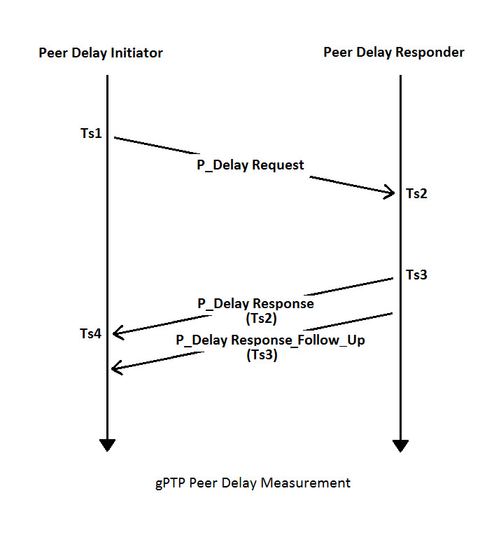 Before synchronisation occurs, each node measures the delay between itself and the adjacent node (or nodes, in the case of a switch) using the peer delay mechanism. This involves an exchange of timestamped messages as shown below.
At the conclusion of this exchange, the peer delay initiator is in possession of all four timestamps, and calculates the delay between itself and its neighbour as follows:
The ‘rateRatio’ in the above calculation refers to the difference in frequency between the initiator and responder clocks. This is determined by comparing the interval between the arrival times of successive P_delay response messages, and the interval between the departure times of those same messages (as reported in the P_Delay response Follow_Up messages). The difference between the two intervals is the difference in frequency between the two clocks. As well as being used in the link delay calculation, rateRatio is also used in the computation of synchronised time.
Once every node knows the delay between itself and its neighbour (or neighbours if it’s a switch), time sync proper proceeds as follows:
Node A sends a Sync message to node B, and timestamps its departure (Ts1). Node B receives the Sync message and timestamps its arrival (Ts2). Node A then sends a Follow_Up message to node B. The Follow_Up message contains three pieces of information. First is the ‘preciseOriginTimestamp’, which records the time of the grand master clock when the message was sent. This value normally remains constant as the Sync and Follow_Up messages traverse the network. The second is a ‘correctionField’. If node A is the grand master, the value of correctionField is the internal delay between the occurrence of the relevant clock event (preciseOriginTimestamp) and the actual transmission of the Sync message (Ts1). If node A is not the grand master, then the correctionField value is the delay between the receipt of a Sync message by node A (not shown) and the time of Ts1. This is known as the residence time. The difference in frequency between the GM and the local clock at node A is known as ‘rateRatio’. This is the accumulated value of the peer-to-peer rateRatios discussed in the context of the Peer Delay mechanism (above). The sum of the preciseOriginTimestamp and the correction field gives the synchronised time at node B corresponding to the time Ts1.
 Some time later (less than 10ms), node B sends a Sync message to node C. The message is timestamped by the local clock at node B (Ts3). The correctionField is the difference between Ts1 and Ts3, which is the sum of the link delay between A and B (already known through the P_Delay measurement), and the difference between Ts3 and Ts2 (residence time). Both must be multiplied by the rateRatio given in the Sync message sent at Ts1 to express them in the timebase of the grand master. RateRatio in the Sync message sent at Ts3 is the difference in frequency between the grand master and the local clock at node B.
Making A Packet
 Dante encapsulation in the context of the OSI reference model.Prior to the 1960s, the only communications networks in existence were telecoms networks, which worked on the principle of circuit switching. A phone call between A and B involved connecting a series of intervening links to form a circuit between the two locations dedicated exclusively to that call. If A and B’s respective neighbours also wanted to talk, a second dedicated circuit needed to be established, and so on.
From the late ’50s onward, people began to realise that this was very inefficient: even if the participants talked without pause, an individual call still utilised only a tiny fraction of a circuit’s theoretical capacity. From this arose the concept of packet switching, which involves dividing information into small segments, and attaching enough information to each that they can be individually routed to their destination, and reassembled when they get there. In this way, a single circuit can serve multiple communication sessions up to the limit of its capacity.
 The Dante network stack.The information added to a data segment in order to form a packet is known as a header. In the same way that a postal address might contain a name, house number, street name, town, district and so on, each narrowing down its intended recipient, so a data packet is typically encapsulated within multiple headers, each relating to some aspect of its delivery and reassembly. The standard way of describing this process of successive encapsulation is as a set of layers, usually represented in the context of the abstract, seven-layered OSI reference model. The diagram above represents the encapsulation of a Dante audio stream within the framework of the OSI model. The corresponding network stack is shown right.
LAN Lord
 Michael Johas Teener.The name Michael Johas Teener may not be familiar to the majority of hi-tech musicians, but his work most certainly is. MJT was the lead architect of FireWire, and chair of the IEEE 1394 standards development effort, and his leadership of the AVB project very much reflects that experience.
Though different in detail, the architecture of AVB — essentially an ‘isochronous mode’ for Ethernet — closely resembles that of FireWire, being based on the same three pillars of guaranteed bandwidth, bounded latency and clock synchronisation. Most tellingly of all, the two share a common transport protocol (see elsewhere in this article). Taken altogether, it’s not unreasonable to view AVB-enabled Ethernet — rather than Thunderbolt, as some have contended — as the true successor to FireWire. Either way, it’s very much a continuation of the legacy of MJT as an unsung benefactor of the modern musician.