Ground Control
Most stage boxes have metal cases that need to be grounded in some way, so there is the possibility of ground loops again, depending on how that is achieved. Moreover, stage boxes are inherently connected to lots of different sources, some of which might also be unbalanced and grounded themselves. So the next step was to reconnect the stage box to the Apollo, with the dummy source plugged into channel 1, and disconnect everything else from the stage box to remove any possibility of external ground loops at the box itself.
The hum persisted, which meant that the problem was either in the internal ground wiring of the box itself — which, although possible, was unlikely in a commercially manufactured box — or there was mains frequency interference getting into the multicore cable somewhere between the stage box and the Apollo. As it was easier to examine the route of the multicore than disassemble the stage box, I climbed behind the equipment rack again, this time to examine the multicore cable, at which point the problem quickly became very apparent when Paul asked: "What is that device lying on the multicore?"
Mortal Coil
Since the stage box came with a multicore cable that was rather longer than Alex needed in his studio-cum-control room, he had coiled up the surplus very neatly and stowed it on the floor directly behind the preamp rack. That, in itself, wasn't a problem, but at some later time he had casually placed a mains plug board right onto the middle of it, and that plug board was carrying a 110V step-down transformer shrouded in Gaffa tape!
 The culprit: a large step-down transformer, which was inducing the hum in the multicore cable.
Remember what I said earlier about stray magnetic fields from mains transformers getting into mic input transformers? Well, it applies to mic cables too. While our original prognosis involving ground loops turned out not to be the case this time, we were right in expecting something related to the newly installed stage box.
 Relocating the mains plug board a few feet away from the coiled multicore completely cured the problem.So, while listening to the hum emanating from the preamp I simply reached down and lifted the plug board and relocated the step-down transformer away from the multicore, whereupon the hum faded out gracefully. Relocating the mains plug board a few feet away from the coiled multicore completely cured the problem — much to Alex's relief and some mild embarrassment!
Perfectly Balanced
'But shouldn't balanced cables reject external interference?' I hear someone ask. In a perfect world the answer should be 'yes', and a well-engineered system like the stage box multicore and Apollo preamp does reject most electromagnetic interference very well. However, this was a pretty extreme situation because the magnetic field strength was both abnormally high and abnormally close to the cable! If you want to know more about the physics involved, see the side box for an explanation.
Having reorganised the jumble of cables behind the preamp rack — paying careful attention to route the mains cables well away from the audio cables, and keeping all the plug boards and power units as far away from the mic cables as possible — we reconnected things at the stage box and worked through all of Alex's mics to make sure everything was hum free. The four inputs to the Apollo were all clean, so we powered up the Focusrite and checked the four inputs to that. Alex told us that he'd recently stopped using the Focusrite because it had appeared to be unreliable, but it powered up okay and everything was also hum free. However, channel 2 was clearly unhappy, producing lots of nasty bangs and splats, but no audio.
Fortunately, Paul quickly realised that the nasty noises only occurred when the XLR was moved in the corresponding mic's own XLR output socket. It appeared that some of the (budget) ready-made XLR cables Alex had purchased recently didn't fit well into the XLR connector of his sE4400, and that the mic wasn't receiving phantom power reliably as a result — hence all the bangs and splats, as the mic couldn't power up properly. Alex had a few Van Damme cables in his collection fitted with Neutrik connectors, and swapping one of those for the cheap cable instantly cured the problem, fitting perfectly and allowing the mic to function as it should!
Tackling problems like this requires a methodical and patient approach...
Clock & Roll
With that small problem resolved, we moved on to checking the Audient preamp, which was connected to the Apollo via a pair of ADAT lightpipes. Alex told us that he had a lot of problems with the Audient, with glitches and losing channels part way through a recording, and the clocking status flag in the Apollo's input routing menu page would flash most of the time. This is all symptomatic of significant clocking problems and, in my experience, the most likely culprits are either poor–quality lightpipe fibres/connectors, or dust in the optical ports.
Investigating the connections involved another clamber around the back of the rack, whereupon it became immediately obvious that, while Alex's two fibres plugged into the Audient's two ADAT outputs with a reassuringly secure click, both were very loose in the Apollo's input sockets and moved around easily — and that made the connections very unreliable. If you're wondering why there were two ADAT lightpipes involved, Alex had resorted to using two in a desperate attempt to make the system work reliably, but actually a single connection was all that was required to convey the eight audio channels and embedded clocks when working at base sample rates (44.1 and 48 kHz).
When I held a single lightpipe fibre in place the system worked correctly and reliably, with the Apollo slaved solidly to the Audient's ADAT clock and no more missing channels or flashing lights on the Apollo's control panel. So the system itself was fine, it was just an issue with the physical lightpipe connectors. Although the dimensions of the JIS F-05 plugs used on ADAT cables are tightly specified, not all manufacturers maintain tight tolerances, so the easiest solution in this case would probably be to simply replace the existing lightpipes for others of a different brand in the hope of them fitting more securely into the Apollo's sockets. We left that one for Alex to explore after we'd gone.
Moving On
With those problem cleared up, Alex asked if there was any simple way to improve the room acoustics, but without doing anything too extreme as he planned to relocate the studio at some near-future date. He'd already built limp-mass membrane bass traps into all four corners of the studio, and had several home-made broadband absorber panels hung on the walls around the studio. However, none were located at the strategic mirror-points, and there was a window at the right–hand 'mirror' point.
As Alex was obviously very handy on the DIY front we suggested he use medium– or high–density mineral wool placed in frames and then covered with breathable fabric to make up some basic mid/high traps. Normally these would go on the left and right walls just forward of the mixing position to intercept the more direct reflections from the speakers, but Alex didn't want to lose his view out of the right–hand window. However, as a window can contribute very strong reflections we suggested he use something like a foam panel or lightweight DIY trap that could be hung in place temporarily — only when mixing — so that he could enjoy the view while composing. Another alternative would be to use heavy slatted blinds, which can be half-closed when mixing to deflect and break up reflections.
Other potential early reflection points include the ceiling and the walls directly behind the speakers. The latter are easily treated with more DIY broadband traps, while the ceiling can either be addressed using a lightweight foam panel or a DIY trap made from 50mm high–density mineral wool of the type used for cavity wall insulation. This would usually be situated directly above the engineer's knees. High–density mineral wool is rigid enough to keep its shape and only needs a fabric covering to keep loose fibres from escaping and to make it cosmetically acceptable.
Alex took all these suggestions on board and thanked us for our help, very relieved not only that the hum problem had been resolved but that we'd also found the cause of his mic cable crackles and optical sync problems.
Reader Reaction
 Alex Attwood enjoying some peace and quiet in his hum-free studio.Alex Attwood: "Not being especially gifted in the physics department, I was becoming worried that I would have to spend the next 40 years EQ'ing out hum from my recordings. It is such a relief to have the issue solved without the need for a soldering iron or replacing gear — thank you Hugh and Paul.
"As a composer, it's generally just you in the studio, so when things start to rattle and buzz without you having asked them to it can leave you at a bit of a loss. Thank goodness for the SOS Forum and travelling editorial team!"
Electromagnetic Interference
A popular misconception is that the outer screen of a balanced cable stops any and all interference from getting into the signal wires, but that's not quite true. The reality is that the cable screen is really only effective against capacitively-coupled electrostatic interference (mainly radio–frequency signals) reaching the two signal wires, and it doesn't do anything useful to protect against electromagnetically coupled interference.
 Instead, the best way of dealing with electromagnetic interference is to twist the two signal wires together. This is because the magnetic field strength diminishes with distance from the source, so if the signal wires just lay parallel, side by side, the closer wire would receive a stronger magnetic field than the more distant wire, and thus a larger signal voltage would be induced in one than the other.
That would be a problem because a differential (balanced) input in a preamp is designed to amplify the voltage difference that exists between the two signal wires, but reject anything that is the same — the so-called 'common-mode' signal. In the situation above, there would be a differential signal, and so any induced hum would become audible.
However, by twisting the two signal wires together, each wire experiences, on average, the same overall field strength. If that can be achieved the unwanted electromagnetic interference will appear as a common-mode signal — meaning the same voltage is induced into each wire — and it will be rejected by the differential receiver, so no audible hum. Most of the time this simple arrangement works remarkably well, and it is employed almost universally, not just in balanced audio wiring, but in many other systems too — including Ethernet cables, for example.
Unfortunately, though, the simple expedient of twisting the signal wires together only works if the interference source is a relatively long way from the cable. In situations where the interference source is located very close to the cable — as happened with the mains transformer and multicore in Alex's studio — the magnetic field strength is so great that, even despite the twisting, one of the signal wires still picks up slightly more interference than the other. This results in a differential interference signal, rather than a common-mode one, and consequently the differential receiver in the preamp can't reject all the interference and the unwanted hum becomes audible. Which is exactly what had happened!
In Alex's case it was easy to move the interference source far away from the cable, but that's not always possible. Twisting the two signal wires together with a much shorter 'lay length' can help, but there are practical limits over how tight the twisting can be. Instead, a better solution — and one which has actually been in use for nearly a century, since the early days of telephony — is an arrangement called 'star-quad'.
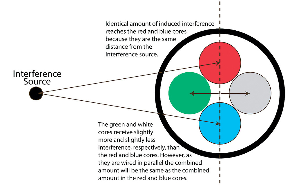
A star-quad cable has four signal wires instead of two (hence the 'quad' part of the name), as well as the usual overall screen. These four cores are twisted together very tightly — far more tightly than a standard mic cable — with a very short lay length. The four signal wires are effectively arranged in a cross formation, with the opposing cores wired in parallel to form a single balanced pair. Most star-quad cables use two white core wires for one pair and two blue wires for the other, while a few use red and blue wire for the hot side, and green and white wires for the cold.
To understand how star-quad works, imagine that the two wires forming the 'hot' connection happen to lie vertically above one another. If an electro-magnetic interference source is placed alongside the cable, these two wires will pick up equal amounts of interference because they are exactly the same distance from the source. However, the 'cold' pair in the cable will be horizontal, and with one core slightly closer to the interfering source, while the other will be slightly further away, the different distances being equal but in opposite directions relative to the position of the 'hot' cores.
So, although the more distant 'cold' wire will get slightly less induced voltage and the closer one slightly more, the fact that they are wired in parallel means the actual voltage conveyed will be the average of the two, and that should be exactly the same as the induced voltage into the two hot wires located midway between the two cold wires. The result is that the differential receiver sees a common-mode signal, and the interference is rejected much more effectively.
Foot Control

 Sitting on the floor in front of a Mid-Sides array that Alex had set up to record a variety of acoustic instruments was an attractive and solid-looking home-made pedal device with four distinct footswitches. Naturally, we were both intrigued and Alex explained that he had made it to allow him to remotely control Logic to record and play back tracks, instead of having to return to the Mac on the desk each time he wanted to record a new take.
I noticed that the connection to this impressive DIY pedal was via a USB connector, so I asked what technology Alex had used within the pedal? All was revealed when he lifted the four switch panels — which were hinged at the rear — to expose a standard Mac keyboard embedded in the thick wooden base-board. Each of the hinged footswitch panels had a carefully placed screw that extended just far enough to depress a specific key on the keyboard when the pedal was pushed down. Those keys were mapped to operate the required functions in Logic, with (from left to right) Cycle (C), Play (space bar), Record (Enter), and Stop (full stop). Stiff springs at the front edge of the base-board ensured that the pedals didn't press on the keys in their resting state.
A simple but clever and beautifully engineered solution to a very familiar problem!