Analogue warmth seems to be the Holy Grail in these digital days. But what is it, why does it hold such appeal, and how can you use it to enhance your recordings?
Get a group of recording engineers together, and sooner or later the conversation will turn to a discussion (probably quickly escalating to an argument) about 'analogue warmth' and how things sounded so much better 'BD' (Before Digital) — and even engineers and musicians who've never worked in earnest with all‑analogue systems (digital having become mainstream as far back as the 1980s) seem keen to bring this perceived 'warmth' into their productions.
What Is Analogue Warmth?
Not everyone has had first‑hand experience of magnetic tape recording and other analogue recording technology, of course, but we've all heard and admired the vast back catalogue of classic records made using this technology from the 1950s onwards.
There are many factors that combine to create character in recordings, ranging from instruments, musicians and performances, through the rooms and mics used, to the preamps, processors and effects (and the way in which they're used), but when we talk about analogue warmth, we're usually referring to the character that the analogue processing/recording equipment and the recording medium add to the sound.
In this article, I'll look at some of the key analogue technologies often associated with 'analogue warmth', and explain why they create the sound they do. Hopefully, this will enable you to make more informed gear choices and create mixes with an analogue feel, if that's what you're after. Some of 'the science' may seem daunting, but the alphabetical 'Technical Terms Explained' boxes should help with that.
Analogue Versus Digital
I cut my professional teeth on analogue equipment, but I think modern digital recording is a significant step up from the best of analogue in many practical ways. A lot of the early digital gear certainly didn't live up to the hype that surrounded it, but understanding and technology have come on in leaps and bounds since then, and to my mind digital recording systems can now deliver pretty much all that was once promised: a near‑perfect recording medium that gives back exactly what was recorded.
That's great in some circumstances, but it's not always what we want: in many cases, the technical limitations and imperfections of analogue systems have become an integral part of the quality of the recorded sounds that we all grew up with — and the end result is perceived by many people as being more pleasing than we can easily achieve today with all‑digital recording chains. Further than that, some of the sounds resulting from 'abuse' of analogue gear have become recognised effects in their own right (tube overdrive and tape saturation being obvious examples).
Interestingly, sound recording isn't the only industry that has found this. Digital cameras and imaging software usually provide a range of 'picture‑style image processing' options. My own camera offers Standard, Portrait, Landscape, Neutral, Faithful, Monochrome, and three user‑defined modes, for example, each changing the tonal balance, colour saturation, sharpness, and contrast in different ways, to enhance the subject.
In short, enjoyment of an artistic product (be it a sound recording, a photograph, a film or whatever) isn't necessarily about precision and accuracy: more often, it's about mood, character and subtle enhancements that make the end result more vivid and interesting than real life.
When it comes to audio, some aspects of analogue technology introduce artifacts and distortions that are perceived as pleasant, and are often musically enhancing — and this is something that lies at the heart of the idea of 'analogue warmth'. Of course, mechanical equipment can be expensive or impossible to acquire, and a hassle to maintain or use. Small wonder, then, that so many people seek (and so many manufacturers now provide) software and hardware tools that aim to reintroduce some 'analogue character' into digital production chains. Some of it works well, some of it not so well — but what is it actually trying to emulate?
Heat Factors
Until now, I've talked rather generically about analogue equipment — a term that encompasses a whole world of microphones, tape, valves, transformers and other electronics. Take a look at the diagram of a reasonably simple analogue recording/mixing chain elsewhere in this article, and you'll see why: multiple opportunities exist to add colour and character to a signal before the master recording is created. There are clearly several factors that make up 'analogue warmth' and our ears almost certainly require a combination of all of them; focusing on only one doesn't seem to deliver a truly convincing result. I'd sum up the most important factors as:
- Magnetic recording tape, and the mechanical artifacts of the tape machine itself, such as flutter and other speed‑stability issues.
- Harmonic and non‑harmonic distortions, such as those caused by transformers and inductors.
- Active circuitry, whether it includes valves (vacuum tubes) or solid‑state devices.
Alongside these, we also have to consider frequency response and dynamics. Ribbon mics, monitor speakers, recording tape and many valve‑stages dating from the 1950s and '60s often had restricted high‑frequency performance and a fuller bottom end, for example, and they also tended to reduce the dynamics of signal transients, through thermal or magnetic 'saturation compression' effects.
As well as the direct influence this equipment had on the sound, it will also have influenced recording and mix decisions, such as mic selection — with brighter‑sounding condenser microphones being chosen, for example, or high‑frequency EQ boosts being applied with the knowledge that the top‑end emphasis and transients would be smoothed by the recording chain.
The Reel Thing
 Of the three factors I've listed above, the one most obviously absent in recording chains these days is the analogue tape recorder, with professional machines now too expensive and maintenance‑intensive for most people to consider practical.
Most audio aficionados are probably aware to some extent of the sonic influence of magnetic tape, but fewer will have considered the influence of the tape machine itself. The biggest problem for any mechanical tape transport system is speed control, and the imperfect nature of this control produces artifacts that are generically lumped together as 'wow and flutter'. There are actually four distinct variants of this, namely 'drift' (which shows up below 0.1Hz), 'wow' (0.1‑10Hz), 'flutter' (10‑100Hz), and 'scrape flutter' (in the 1‑5kHz region). To explain the last term, which you may not have heard, as tape is dragged across the tape heads under tension, its movement sets up a vibrational resonance along the length of unsupported tape between the heads and/or the preceding rollers or guides — just like a violin string being excited with a bow. This resonance will tend to cause the tape to vibrate against the head, effectively causing it to move in a series of short, rapid jerks, which we call scrape flutter.
Fifty years of tape‑machine design evolution reduced wow and flutter to extremely low levels by the 1980s, but it couldn't be removed completely, and even the mighty Studer A820 two‑track machine's specifications quoted a wow and flutter figure of 0.04 percent when the tape was running at 15ips (inches per second). This is a tiny amount, certainly, but word‑clock stability — which is the equivalent of wow and flutter in modern digital systems — can't even be measured, as digital systems are orders of magnitude more stable in the time domain.
 Using one analogue technology to mimic another: Rupert Neve Designs' Portico 5042 uses inductively coupled coils to emulate constant current drive to a tape machine's heads.So what audible effect would such low levels of wow and flutter introduce? Well, the minute cyclical speed fluctuations of flutter, and particularly scrape‑flutter, create subtle 'side‑bands' (see 'Technical Terms' box) and noise modulation around the recorded audio. These add a perceptible low‑level 'grunge' to the sound, and while better-designed and maintained tape machines suffered lower levels of this grunge, it was always there to some extent. Although technically flutter is a fault, many argue that its side‑bands and noise‑modulation effects are an intrinsic part of the sound character of all analogue tape recordings, and that we've come to accept (and expect) them as part of recorded sound — and as part of what we call analogue warmth.
The more bounce‑downs that are done on the same tape, the stronger these effects become, as each recording pass adds to the grunge, and this made the associated sound character more prevalent in the late 1970s and the 1980s, when large multitrack recording formats became commonplace and lots of overdubbing and bounce‑downs were routine.
These once‑common recording attributes are absent from all digital recording chains, and I don't know of any software plug‑ins that claim to recreate the specific grunge effects of wow and flutter. A few claim to include some element of wow and flutter in some operating modes — one such example being Digidesign's Reel Tape Suite — but to date I've not heard one that I've found truly convincing in this respect.
Tape Saturation
Most people reading this article will have heard about the idea of tape saturation, and the key role it plays in creating 'analogue warmth'. This is another complex area, but one that more companies have been successful in simulating, both in analogue hardware and in digital plug‑ins. Analogue recording tape is inherently 'non‑linear', its effect being determined by a combination of tape formulation, record and replay head construction, tape speed, tape width, record and playback equalisations (and phase shifts), and the level and waveform of high‑frequency bias. Plenty of variables to play with there! These parameters introduce distortions of harmonic content (particularly at low frequencies), and frequency and phase‑response irregularities, and they reduce dynamic range, mainly affecting high‑frequency transients through magnetic saturation and 'self‑erasure' effects.
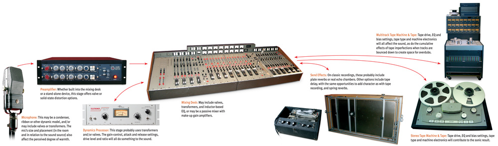
 also affect the perceived degree of warmth.") Microphone: This may be a condenser, ribbon or other dynamic model, and/or may include valves or transformers. The mic's size and placement (in the room and in relation to the sound source) also affect the perceived degree of warmth.
Microphone: This may be a condenser, ribbon or other dynamic model, and/or may include valves or transformers. The mic's size and placement (in the room and in relation to the sound source) also affect the perceived degree of warmth. Preamplifier: Whether built into the mixing desk or a stand-alone device, this stage offers valve or solid‑state distortion options.
 Mixing Desk: May include valves, transformers, and inductor‑based EQ, or may be a passive mixer with make‑up gain amplifiers.
 Dynamics Processor: This stage probably uses transformers and/or valves. The gain‑control, attack and release settings, drive level and ratio will all do something to the sound.
 Multitrack Tape Machine & Tape: Tape drive, EQ and bias settings, tape type and machine electronics will all affect the sound, as do the cumulative effects of tape imperfections when tracks are bounced down to create space for overdubs.
 Send Effects: On classic recordings, these probably include plate reverbs or real echo chambers. Other options include tape delay, with the same opportunities to add character as with tape recording, and spring reverbs.
 Stereo Tape Machine & Tape: Tape drive, EQ and bias settings, tape type and machine electronics will contribute to the sonic result.Most professional tape machines are aligned to be slightly 'over‑biased', as this minimises low‑ and mid‑frequency harmonic distortions (see box above). However, this optimisation of distortion is at the expense of high‑frequency extension and transient accuracy — and provides a 'warmer' sound character than the flat and linear response of digital systems. The difference in frequency response isn't huge, but the gentle shape of the response curve and its associated phase response is such that it is generally perceived as providing a warmer sound than that of a near‑perfect digital system.
Other common artifacts introduced by the complex signal processing required in an analogue tape recorder include the potential for high‑frequency ringing in the record pre‑emphasis equalisation, a mid‑range bulge in the frequency response (more obvious with slower tape speeds) due to the nature of the bias, and often significant third‑harmonic distortion on loud low‑frequency components of the recorded sound.
Although frequency response is an important element of the impression of warmth, and very small changes, of a decibel or less, can often make a big difference to the perception of the sound character, the overall tonality is not, in itself, enough to introduce warmth. If it were, all we'd have to do is modify the frequency response of our digital systems appropriately and the complaints of 'digital sterility' would all go away! While frequency response clearly plays a role, the effect that analogue recording has on signal transients is — in my view — far more important.
Loud high‑frequency transients simply don't survive magnetic tape recording, in most cases. Magnetic saturation does the initial damage and 'self‑erasure' takes care of the rest — which is why the first playback from an analogue tape might sound crisp and lovely, but subsequent playbacks tend to lose some impact and vibrancy. Looked at in another way, the top end inherently becomes less brash as the transient detail is reduced in level and impact, contributing to our magical analogue warmth character. Of course, digital systems retain that transient 'edge' detail regardless of how many times a recording is replayed.
There are plenty of tape and tape‑saturation plug‑ins to try, including Crane Song's Phoenix Tape Emulation, McDSP's Analog Channel, PSP's Vintage Warmer, Voxengo's Tapebus and Nomad Factory's E‑tube Tape Warmer. I rather like Yamaha's AE021 Master Strip tape emulator plug‑in for their digital consoles too. In the hardware department, Rupert Neve Designs' Portico 5042 is a good offering, as are Crane Song's Hedd and the Anamod ATS1. These all try to emulate the effects of the typical tape‑recording signal‑processing chain and of tape saturation. Some also attempt to simulate the tonal changes caused by different bias level settings, tape types and running speeds. To my mind, although these are all useful tools that do introduce some aspects of familiar analogue warmth, there's still something missing.
Transformers
 Transformers have been an integral part of analogue audio signal paths right from the earliest days, frequently being employed at every input and output. This model is made by Lundahl.Any device that involves magnetic coupling may introduce interesting or troublesome non‑linearities and harmonic distortions into the signal. Transformers have been an integral part of analogue audio signal paths right from the earliest days, frequently being employed at every input and output, as well as between amplifying stages, in many cases. Finding 10 or more transformers in the signal path wasn't uncommon in the 1960s and '70s!
Harmonic distortion in transformers is caused by two effects: hysteresis for low‑level signals and saturation for high‑level signals (see 'Technical Terms' boxes). The effect is always greatest for low frequencies, and results mainly in third‑harmonic distortion. Lots of factors in the design of a transformer affect the level of audio distortion, but key amongst these is probably the material used for the magnetic core. Core metals with a high nickel content typically result in the least hysteresis distortion (but tend to be relatively expensive), while simpler, soft‑steel cores tend to give far higher distortion figures but are much cheaper. The factors associated with transformer distortion and character are many and varied, and you can read about them in the 'How Transformers Distort' box below.
Active Gain Stages
Active gain stages (basically, another term for amplifier) usually introduce a degree of distortion as part of the business of raising signal levels (see 'How Amplifier Stages Distort' box), but the nature of that distortion varies considerably, depending on the circuit topology, the kind of active devices employed, and even the nature of their power supplies. One such device is a valve, or tube, and most people associate valve amplifiers with the concept of analogue warmth, but it's entirely possible to design solid‑state circuitry using discrete transistors or integrated circuits that can sound just as 'warm', if required, and there is plenty of solid‑state vintage equipment associated with analogue warmth, not least being classic Neve mixing consoles, for example, without a valve in them. So don't assume that if it doesn't have valves it won't sound good. I have built and repaired valve amplifiers that definitely didn't sound very nice, before or after, and have bought solid‑state designs that do, so it's much more complex than just using valves everywhere!
Valves come in a number of varieties, but the most common in audio applications are triodes (such as the ECC83/12AX7), beam tetrodes (the KT88/6550), and pentodes (such as the ECL86).Triodes are normally used for mic‑ and line‑level gain stages, while beam tetrodes and pentodes are more often used for power amplifier output stages, although any could be employed in more or less any role, given appropriate circuit designs. The important point is that triodes tend to be used in single‑ended circuits and produce quite a lot of both even and odd harmonic distortions, while beam tetrodes and pentodes are normally used in so‑called class A or AB 'push‑pull' power‑output circuits, which cancel out the even harmonics, leaving only the odd‑harmonic distortions. (Look at the 'Understanding Harmonic Distortion' box for more on the different types of distortion and the 'Vacuum Tubes' box later, for more background on valves.)
Similarly, solid‑state devices (bipolar and field‑effect transistors, and their large‑scale integrated circuit relatives) are used in different circuit topologies that tend to dominate the kind of harmonic distortion they produce. Indeed, the circuit topology is far more influential over the amount and character of distortion than the type of active device actually being used. In class‑A topologies, for example, the level of distortion components falls with reducing signal level, whether valves or transistors are being used. Quiet signals have little distortion, while louder signals suffer more distortion. However, in class‑AB circuits, the amount of distortion remains more or less constant, regardless of signal level, so the distortion components become far more audible as signal level falls. On top of this, in class‑B topologies that exhibit 'crossover distortion', the distortion productions may be not musically related to the source signals at all ('anharmonic'), which sounds very unpleasant and definitely not warm!
So the circuit topology determines the kind of distortion products made and how they vary with low signal levels to a large extent, but there are other factors too. What happens with large signal levels is another important area to consider. A valve circuit's working dynamic range is reasonably linear and usually very wide, but very loud signals exceeding that linear range move into a region that curves fairly smoothly into saturation. Eventually the signal will reach full clipping, but initially the distortion rises relatively gently with low‑level harmonic distortion and musically 'friendly' intermodulation products. Guitar amps are often used in this non‑linear region quite deliberately, because of the pleasing effect it creates.
Most solid‑state circuits operate on far lower voltage rails and peak signal excursions beyond the intended linear working range immediately enter a very abrupt non‑linear region, and this usually results in fairly aggressive high‑level harmonic distortion and nasty intermodulation effects. It's possible to design solid‑state circuits that overload rather more gracefully but, sadly, they aren't very common outside the esoteric equipment ranges.
Yet another factor in all this is the audible impact of negative feedback or NFB (see 'Technical Terms Explained' box). Valve stages — especially triode‑based designs — generally don't use or require much, if any, NFB. Solid‑state designs, on the other hand, especially the early ones, have tended to use rather a lot of NFB. As a result, most valve amps tend to have a higher base level of harmonic distortion than most solid‑state designs, essentially because NFB is intended to reduce harmonic distortion. However, high levels of NFB can lead to other issues, including damage to high‑frequency transients and effects on the transient dynamics of complex signals. Modern solid‑state designs tend to use much lower levels of NFB, partly because the active devices have been improved to the point where they no longer require it to deliver acceptable results. Consequently, the transient behaviour of modern solid‑state designs more closely resembles that of valve amps, while still having lower overall distortion levels.
Power‑supply design can also be a big factor in overall sound quality. It's not unusual, for example, for vintage valve power amps to suffer from saggy power supplies that dip when handling loud signals, resulting in a kind of dynamic compression or even a dynamic modulation effect. But the problem isn't limited to valve amps, and is potentially worse for solid‑state designs, because they tend to operate with lower supply voltages and higher supply currents, while valve amps require the reverse.
Lessons From Yesteryear
As I said earlier, the science underlying this fascinating subject is complex —and had I sufficient space I could go on — but I've described what I believe are probably the primary participants in that mysterious sound character we refer to as 'analogue warmth'. I also said at the outset that I think it is a combination of many (or even all) of these factors that's required to simulate this warmth adequately. Harmonic distortion is clearly a key player — but it's not just one kind of harmonic distortion, or distortion for one set of signal levels.
Transformers tend to thicken up low‑level sounds more than high‑level ones, while some active gain stages (particularly triode valves) tend to do the reverse. Tape saturation introduces harmonic distortion differently again. Then there are the frequency and phase‑response variations associated with transformer damping, tape recorder equalisation and biasing, active gain‑stage bandwidths, and so on. Finally, there are the complex modulation effects of analogue tape caused by the minute speed fluctuations of scrape flutter. The physics of analogue recording certainly are not simple!
But what does all this mean in practice? Analogue warmth will inevitably mean slightly different things to different people, but I suppose, broadly speaking, that there are three different approaches you can use to try to get analogue flavour into your mix — any of which may be used in combination. The first, most obvious approach, is to try to replicate old techniques: use analogue equipment to make your recordings, and track to multitrack tape — even if you plan to import everything into a DAW later. The second is to do everything after the mic and preamp digitally, using software that emulates the analogue recording chain. The third is to try to 'treat' your complete mix with analogue equipment or emulations.
The first of these is obviously the most authentic approach — although some of the gear that was used on many classic recordings is now prohibitively expensive, even if you can get hold of it (EMT Plate reverb or Fairchild 670 anyone?). The second isn't likely to be wholly convincing in isolation but can yield great results in combination with genuine analogue gear. As for the third, I haven't yet found a single magical processor (whether software or hardware) that instantly transforms a 'sterile' digital mix into one with wonderful, genuinely analogue warmth (although there are several that do work very well). Personally, I prefer routing a mix through a high‑quality analogue device of some kind, and often one with transformers in it.
Preamps, compressors and summing mixers all seem to have the desired effect too, even with any signal processing turned off, as the inherent properties of the analogue circuitry seem to impart a beneficial and satisfying character to a mix. It would be nice to achieve the same effect in the digital domain, and a lot of effort is being put into software design for exactly this purpose right now. However, with modern audio interfaces, the old arguments of keeping the number of A‑D and D‑A conversions to a minimum don't really apply: there's no perceptible quality loss now for many, many generations of conversion — so it makes sense to me to go analogue to achieve the character we associate with analogue equipment.
Understanding Harmonic Distortion
Any non‑linear audio system, such as an analogue tape recorder, will distort the input signal to some extent, and because that means changing the shape of the audio waveform, it normally results in the creation of additional harmonics. To simplify, harmonics are multiples of the source ('fundamental') frequency that make the sound more complex, which might or might not be pleasing to the ear. Harmonics at two, four, six and eight times (and so on) the source frequency are called even‑order harmonics, while those at 3, 5, 7, 9 (and so forth) are odd‑order harmonics. Some non‑linear systems tend to generate more even‑order than odd, and others more odd than even, with the balance between even‑ and odd‑order harmonics strongly affecting the sound quality.
Describing distortion in words is like describing the flavours of cheese through the medium of dance, but I'll try. The harmonic content of a signal is what gives a sound its timbre, or character: it's what makes a flute sound different from a clarinet, for example. Harmonic distortion, as you might expect, is a distortion of a signal, via the introduction of extra harmonics or the enhancement of those already present, resulting in a change in timbre. Even‑order harmonic distortion tends to sound musically sympathetic, smooth, and bright in a constructive way. Many simple valve‑based circuits (including most using triodes) tend to generate mostly even‑order harmonic distortion. Odd‑order harmonic distortion tends to sound rough or harsh, gritty or edgy, and is often associated with added 'richness' and 'depth'. Many early (1960s/1970s) transistor amplifiers tended to generate mostly odd‑order distortion when overdriven, giving the transistor a 'bad reputation' at the time. The nature of the non‑linearities in magnetic tape recording results in predominantly odd‑order harmonic distortion, and most tape‑recorder alignment procedures use the level of third-harmonic distortion as a reference measurement for alignment.
The reality is more complex, though, because the type of distortion produced depends only partially on the type of active device being used: it also depends heavily on the overall circuit design, and it's perfectly possible to produce transistor‑based circuits that generate mostly even‑order harmonics, or valve circuits that produce mostly odd‑order harmonics — or both types of active device can be used in extremely linear and very low‑distortion circuits. Similarly, even‑harmonic distortion can be manifest in tape recorders, but it rarely dominates. If present, it's usually caused by distortions in the amplifying circuits (most commonly in valve‑based tape recorders), or as a result of magnetised heads.
No mention of distortion in tape recorders would be complete without a note about the practical implications. In setting up a tape recorder — whether a stereo mastering machine or a multitrack — the studio engineer will normally try to optimise the settings to minimise distortion. (It's what engineers generally do!) The minimum distortion for a given tape type will be with a specific combination of record level, record equalisation, and bias level. Of those, the only variable which the user can adjust easily from outside the machine is the record level, and by driving a higher signal level into the tape recorder (recording 'hot') the tape itself can be overdriven to encourage higher levels of distortion and transient squashing. How hot, and how much distortion, is obviously a matter of taste and judgement — although I would warn against over doing the effect, because a little tends to go a long way.
Something else to be aware of is that some of the last generation of high‑output tapes require a huge amount of record signal to drive them well into saturation, but not all machines will have sufficient headroom in the record electronics (or even in the magnetic heads themselves to cope). This can be an issue with some Revox machines, for example. So the choice of tape type for a given tape recorder is important if you are looking for deliberately overdriven effects.
Where Does Warmth Come From In An Analogue Recording Chain?
How do I add warmth to my sound? Study the diagram below — which provides an example of a relatively simple analogue recording and mixing chain — and you'll see how many different stages there are at which analogue warmth of one sort or another may be added to the sound of a recording, even before you start to consider the nature of the spaces in which the recordings are made.
How Amplifier Stages Distort: Valve Versus Transistor
The chart below compares the distortion ratio at 50Hz of two mic preamps: a Dbx 386 and an AEA TRP. Both have electronically balanced inputs and outputs (there are no transformers), but the Dbx 386 employs a 12AU7 (ECC82) triode valve running with a 200V anode supply voltage as part of its gain stage, while the AEA TRP is a DC‑coupled, JFET, solid‑state design. For this test, both were providing just under 58dB of gain.
 This chart compares the distortion ratio at 50Hz of two mic preamps: a Dbx 386 and an AEA TRP.
The obvious point to note is the way the distortion percentage falls linearly as the signal level rises for both units, until the input signal reaches about ‑64dBu. The AEA preamp distortion percentage continues to fall linearly (and virtually identically to the GML preamp mentioned in the 'How Transformers Distort' box), but it starts to rise dramatically in the Dbx. (This is quite intentional, a deliberate feature of this unit, and occurs because the valve stage is being driven harder to produce greater levels of harmonic distortion.) Not surprisingly, the AEA TRP sounds supremely clean and transparent at all signal levels, while the Dbx becomes progressively richer and thicker sounding as the input level rises, or the drive control is advanced. If you were asked to choose which sounded warmer and more analogue, the Dbx would win hands down! The result sounds fabulous on a variety of instruments and voices and it's one of my favourite preamps for situations that call for this kind of 'analogue warming.'
How Transformers Distort
The graph below compares the low‑frequency distortion ratio at 50Hz versus signal level between ‑75 and +20dBu for a Radial Pro‑D2 passive DI box (purple trace) and a Canford Audio Line Isolating Transformer (brown trace). The devices are intended to satisfy different technical demands, but they are similarly priced and sized, and both feature a line‑level transformer.
 and a Canford Audio Line Isolating Transformer (brown trace).") This graph compares the low‐frequency distortion ratio at 50Hz versus signal level between ‐75 and +20dBu for a Radial Pro‐D2 passive DI box (purple trace) and a Canford Audio Line Isolating Transformer (brown trace).
This graph compares the low‐frequency distortion ratio at 50Hz versus signal level between ‐75 and +20dBu for a Radial Pro‐D2 passive DI box (purple trace) and a Canford Audio Line Isolating Transformer (brown trace).
In both cases, the amount of distortion increases as the signal level falls, due to hysteresis, so quieter signals end up sounding slightly richer and denser, thanks to the additional harmonics. At higher signal levels, the distortion starts to rise again, but far more gradually. The Lundahl transformer in the Canford unit exhibits a much lower distortion level overall than the custom‑designed transformer in the Radial unit (one percent, as opposed to 60 percent at ‑75dBu), but they both clearly follow the same trend. Interestingly, the Lundahl transformer also exhibits a much broader region of minimum distortion. I'm not suggesting that one of these units is necessarily better than the other in all respects, just pointing out that this demonstrates quite clearly the kind of audible impact a transformer can have — and that transformers vary enormously in their sonic quality and influence.
Transformers are inherently inductive, so their frequency response depends on the input and output impedances of the circuit surrounding them. The most critical aspect of this is the high‑frequency damping characteristic. If the load impedance is too low, the response will tend to form an under‑damped resonant peak just below the cut‑off frequency, and if the load impedance is too high it will over‑damp the output, resulting in an early roll‑off. An under‑damped transformer will produce ringing on HF transients, so the tendency is to over‑damp rather than under‑damp, and hence the likelihood is of a slightly reduced bandwidth.
There aren't really any response issues at the low end (providing the transformer is designed to handle the likely level of low frequencies without saturating) but, interestingly, a transformer exhibits much less low‑frequency phase distortion than a coupling capacitor designed to provide the same high‑pass cutoff frequency. That may well be yet another element of the 'analogue warmth' associated with vintage equipment, where coupling transformers rather than coupling capacitors was the norm.
 against the Focusrite ISA428, which features a Lundahl transformer front end.") This diagram compares the distortion ratio at 50Hz between a GML 8304 preamp (transformerless, discrete, bipolar transistor design) against the Focusrite ISA428, which features a Lundahl transformer front end.
This diagram compares the distortion ratio at 50Hz between a GML 8304 preamp (transformerless, discrete, bipolar transistor design) against the Focusrite ISA428, which features a Lundahl transformer front end.
The diagram above compares the distortion ratio at 50Hz between a GML 8304 preamp (transformerless, discrete, bipolar transistor design) against the Focusrite ISA428, which features a Lundahl transformer front end providing 20dB of the gain, before feeding a solid‑state Rupert Neve‑designed preamp. Both units were providing a total of 60dB of gain. The distortion ratio for the GML8304 (lower brown trace) is significantly less than that of the ISA428, and that difference continues to fall as the signal level rises, tracking in parallel with the GML preamp. What this shows is that the input transformer (and possibly the active electronics) contributes to the overall distortion, but in a consistent way. Although the difference in distortion isn't huge on graph paper, when comparing the two units audibly, most would say that the Focusrite ISA428 sounded warmer than the GML 8304.
I've also compared the frequency responses of these two preamps in the graph below, and what that reveals is that the ISA428's frequency response is 0.5dB down at 20kHz compared to the GML. I think this tiny HF response tailoring also contributes usefully to the slightly warmer sound character perceived when comparing these two excellent preamps.
 This graph compares the frequency responses of the ISA428 and GML preamps.
Vacuum Tubes & How They Work
A vacuum tube (usually known simply as a 'valve' or 'tube') basically passes a current from the cathode to the anode: that's all it does. The cathode is persuaded to pass that current as a stream of electrons by heating it up, and that's what the heater filament in a valve is there for. How much current flows from the cathode to the anode is determined by the voltage applied to one or more grids. Triodes have only three terminals: cathode, control grid and anode (hence the 'tri' in triode). The tetrode has four terminals (cathode, control grid, screen grid and anode), while the pentode adds yet another grid, called the suppressor grid. The extra grids in the tetrode and pentode valves are there for complicated scientific reasons, but basically enable higher gains to be achieved and operation at higher radio frequencies than is possible with simple triodes.
Suggested Plug-ins for Emulating Analogue Warmth
There's no magic-bullet 'Warmification' plug-in. As Hugh Robjohns explains in the main text of this article, and the diagram elsewhere also illustrates, several different factors combine to create a perception of warmth. While you may be able to add character with something like PSP's Vintage Warmer or one of URS Saturation's tape emulation models on the master or group buses in your DAW, if you're looking for an authentic fake-analogue sound you really need to 'think analogue' while using your mics and plug‑ins, applying more subtle treatments at different points in your mix. Fortunately, there are plenty of good software tools to help you create believable warmth.
Valves/Tubes: My strongest criticism of even the best software valve guitar-amp emulations is that they lack the immediacy required to make software feel like a real amp when playing — but, happily, that's of no concern if you're processing sounds in the mix! As well as guitar amps and cabinets (which in themselves can be a useful tool for adding analogue character), there are oodles of dedicated valve preamp models too, though do note that it's not possible to replicate in software alone the way a mic interacts with a microphone preamp. At the cheaper end of the scale, Silverspike's Ruby Tube is pretty handy (check this month's Mix Rescue for an example), and moving up in price the offerings from Nomad Factory (Tube/Tape Warmer) and Antares (Warm — based on their earlier Tube) are well worth checking out. Another option, of course, is to use the valve gain-stages of emulations of classic hardware devices (of which more in a moment).
Tape Emulation: Emulating tape is a harder task because of the sheer number of variables, and no‑one has nailed every complexity, right down to convincing wow and flutter. However, there are plenty that offer control over things like tape drive, saturation and hysteresis, and they range from the subtle to the obvious, the almost free to the expensive. Two shareware plug‑ins worth a try are the VST, PC-only Ferox by Jeroen Breebaart and Ferric by Bootsy. The former offers an impressive array of controls, and can yield a great deal of colour, wheareas the latter is simpler but much more subtle. Both have their uses, depending on the effect you seek. Moving up in price, there's Massey's Tape Head (for Pro Tools on the Mac only, also with a free version, Tape Head Medium), the aforementioned Nomad Factory Tube/Tape Warmer and URS Saturation, DUY's DaD Tape and Digidesign's Reel Tape. DUY's offering includes models of four different tape machines, as well as different noise-reduction systems, while Reel Tape offers control over wow and flutter characteristics (not quite like the real thing, but a very useful addition). It might also be worth looking at some of the various tape delay plug‑ins, particularly models of classic units such as Universal Audio's emulation of the Roland RE201 tape echo.
Classic Gear Emulations: I've not seen a software emulation of a Lundahl or Sowter transformer yet (I'm sure it's only a matter of time!), but that's because transformers tend not to be modelled on their own, but in the context of the circuits in which they appear — in other words, if it's the sound of transformers you seek, you need to look at emulations of classic hardware. There are now more such emulations than you can easily count. They vary enormously in quality and price, and, of course, some have extra features such as tube emulation. Some of the best are those for the Universal Audio UAD platform: their Neve, Pultec and Fairchild models in particular, are useful, even when the plug-in's bypass mode (not to be confused with your DAW's plug-in bypass button) is engaged, as well as their Plate 140 reverb. Waves offer several useful suites of plug‑ins modelled on analogue gear (their API range, for example). Abbey Road/EMI, SSL, Harrison and SPL all offer software based on their own hardware, the pick of the bunch, for me, being the Abbey Road plug‑ins. Other manufacturers, such as URS, Softube, TC Electronic and Bomb Factory, also offer well‑known models, but probably the greatest number of 'authentic' emulations for a reasonable budget comes courtesy of a hardware device, the Focusrite Liquid Mix, with its 'dynamic convolution' DSP‑based system.
You might not be aiming to recreate the sound of a specific piece of gear, of course, and there are many manufacturers making plug‑ins that are 'inspired by' hardware: they don't claim to recreate them, merely to offer an approximation of their characteristics. Stillwell's Vibe EQ and 1973 are excellent affordable plug‑ins that fall into that category, and if your budget can't stretch even that far, PC users could do worse than look at the Antress Modern range of shareware plug‑ins: not perfect, but great for the money! Matt Houghton
Technical Terms Explained
Active Gain Stages
'Active gain stage' is just another term for amplifier, and all active gain stages, whether valve or solid‑state, basically work in the same way. The output side of the device conveys power from the power supply, under the direct control of the input signal applied to the grid (valve) or base (transistor). If the input signal gets bigger, the valve or transistor lets through more power from the power supply. Ideally, the relationship between the input and output signals would be perfectly linear, but it never quite works that way. It's not bad (in fact, with clever design and good valves and transistors, it can be made surprisingly linear), but it's never quite perfect — and, as a result, the output signal is never quite a perfect but larger version of the input. It will always suffer some small distortions (see 'Understanding Harmonic Distortion' box). Hopefully, those small distortions will be only 0.0001 percent of the original — and modern circuitry can achieve that quite easily in most cases.
Hysteresis & Bias
In a tape recorder, varying electrical audio‑signal input is converted to a varying magnetic field by the record head. The head is designed to force this magnetic field to radiate across the magnetic tape. As the tape passes, the individual magnetic particles are influenced by that varying field, retaining their state of magnetisation as they leave its sphere of influence. However, the way those particles respond to the magnetic field is not linear: in fact, it's extremely non‑linear in parts. With a very weak magnetising field, they don't bother to get out of bed and do anything useful at all! This is called 'hysteresis'. The magnetic field has to be above a certain level (threshold) before the magnetic particles in the tape recognise and react to it.
Conversely, if the magnetic field is too strong, there won't be enough magnetic particles in the tape to capture all the energy, so when the tape is replayed, they'll reproduce less energy than was originally there, which is the saturation effect. Hysteresis and saturation are often shown diagramatically as the tape B‑H curve, where the H‑axis represents the applied magnetic field and the B‑axis is the retained magnetic field. In a linear system, it would be a straight diagonal line. In practice, it looks something like a hash symbol!
We can't do much about the saturation problem, because there will always be a limit to how many magnetic particles can be embedded into a piece of plastic tape. But the hysteresis problem is usually overcome by the use of 'Bias'. This is a very high‑frequency, high‑level, pure sine‑wave signal, well above the range of human hearing (typically in the range 75‑150kHz for professional tape recorders, lower for cassette machines), which is mixed in with the audio signal being fed to the record head. The idea is that it excites the magnetic particles to capture the varying magnetic field even when the audio signal itself is very quiet. The benefit is that the recording medium is 'linearised' and distortion is reduced enormously. The level of the bias signal is important because it has to be high enough to reduce hysteresis distortion to acceptable levels, but not so high that the frequency response is affected adversely. Being such a high frequency, the bias signal doesn't tend to hang around on the tape (because of self‑erasure, which you can read about elsewhere in this box), and few, if any, replay tape‑heads have a gap between the pole‑pieces small enough to register such a high‑frequency signal. If any of it did get through, it would be very easy to filter out when replaying the tape without affecting the wanted audio. Bias in a tape machine is doing a very similar job to dither in a digital system: it linearises what is inherently a non‑linear recording medium.
Magnetic Coupling
Magnetic fields like to get out and about and interact with everything around them. Passing a current through a coil of wire will generate a magnetic field, and that field generally extends outside and all around the coil. If you place two coils close to each other, the field from one will induce currents in the other (that's how transformers work), but the same is true of a coil and any nearby conductor; it doesn't have to be a coil. This is known as 'magnetic coupling'.
Negative Feedback
One way of helping to make amplifier stages more linear and reducing distortion products is to use negative feedback. The technique employs a signal feedback path from the output of the gain stage back to the input, but in opposite polarity. The concept was invented back in the late 1920s, as practical applications for the thermionic valve were being developed — but the idea translates perfectly to solid‑state electronics.
The basic idea is to compare the output signal with the input signal. The difference between them will be the distortion components that the amplfiier stage has added because of its inherent non‑linearities. By adding that resulting difference signal in the opposite polarity to the input signal, the amplifier distortions can be neatly cancelled out. In this way, the amplifier is made to be much, much more linear, and exhibits a much, much lower distortion. In audio systems, the input signal is changing all the time, and for negative feedback to work accurately, the feedback and 'error cancelling' function has to work infinitely fast. This is a problem, because no one has found out where infinity lives yet! In practice, modern devices and circuits do work very well with negative feedback and do provide a fantastic reduction in distortion. That said, there are those who claim it's the route of all audio evils and that amplifiers with no or only very minimal negative feedback sound much nicer (they may well be right in some cases!).
Pre‑emphasis
The magnetic heads of a tape recorder inherently impose a 6dB/octave rising frequency response, and that has to be corrected in a standard way so that tapes recorded on one machine can be replayed accurately on another. Part of that standard requires that the recorded signal is boosted at high frequencies (a process called pre‑emphasis) and cut by an equivalent amount on replay. Amongst other benefits, this helps to reduce the annoyance of random tape noise and high‑frequency harmonic distortion artifacts.
However, all forms of equalisation involve the storage and release of energy, and will have some degree of resonance. If you hit a bell, the energy imparted by the physical contact is released over time and becomes audible as a ringing sound, and exactly the same thing happens in all kinds of filters — although its audibility varies greatly depending on the design of the filter. Normally, filters are designed not to ring (they are said to be 'critically damped'), but the higher the Q of the filter (the narrower the bandwidth of signals it's designed to affect), the more the tendency to ring becomes obvious. By way of illustration, think of a synthesizer low‑pass filter that can be pushed into self‑resonance...
Saturation Compression
In the case of tape, saturation compression is caused by not having enough magnetic particles to store a stronger magnetic field, while in valve circuits it's because the valve can't move any more electrons from the cathode to the anode. In both cases, the medium basically runs out of supplies and hence becomes non‑linear.
Self‑erasure
Strictly speaking, 'self‑erasure' in a tape machine occurs as the magnetised particles on the tape move away from the record‑head gap. As the magnetic field from the head gets weaker with increasing distance, there comes a point where the field strength is similar to that of the adjacent magnetised tape particles, and there is then a kind of 'virtual record‑head gap' constructed between the real head and the just‑recorded tape itself. This tends to erase newly recorded but relatively weak high‑frequency signals, and the problem is made much worse if the record head or other local metalwork is magnetised (hence the importance of regular demagnetisation of the tape path). The other aspect of tape recordings referred to as self‑erasure is the natural tendency of the tape to lose some recorded high‑frequency energy over time as the tightly wrapped layers of magnetised tape interact with each other: high‑frequency signals tend to have much less energy than low‑frequency signals in most forms of music, and hence are the most easily lost through these effects.
Side‑bands
If you frequency‑modulate one signal with another, the result will contain side‑bands, which can be seen if you examine it in the frequency domain. This is the basis of a wide range of common technologies, including FM radio, digital sampling and ring modulation. For example, if you modulate a simple constant sine‑wave tone at 100Hz with a modulation signal at 10Hz, the result will contain components at 110Hz and 90Hz, these being the side‑bands around the original 100Hz signal, spaced above (sum) and below (difference) by 10Hz.
Tape 'wow and flutter' affects the speed of the original recorded material in a repetitive, cyclical way. Changing the speed also changes the frequency of that original material, so we have a form of frequency modulation going on. The result is to add side‑bands to the original material. Every frequency component of the original will generate sum and difference side‑bands spaced according to the wow‑and‑flutter rate. Since the original audio is likely to be a lot more complex than a simple tone, the generated side‑bands will be equally complex, and they'll generally be very low in level. However, they will inevitably add some complex new spectral components — which are recognised as part of the subtle character of a tape recording.
Transient Dynamics
Transients are brief, loud sounds that inherently have a lot of strong high‑frequency components (think drum‑kits), and are significantly louder than the main body of a recording. In recording systems that have a limited high‑frequency response (such as slowish tape recorders, running at under 15ips), transients are easily damaged and distorted, and will often replay at significantly lower levels. This means a reduced dynamic range on replay: in other words, an alteration to the transient's dynamics. In systems with a non‑linear amplitude response, like tape (which has a linear range up to a certain level but quickly becomes non‑linear above that, acting, in effect, much like a steep‑slope compressor), allowing occasional high‑level transients to transgress the non‑linear region results in compression, altering their dynamics again.