Can an external clock signal really improve the performance of your digital audio devices? We put seven of the best master clocks through their paces to sort out the facts from the myths.
Digital audio clocking is a topic that almost everyone involved in recording has heard of, but that few really understand. I'm often asked how different devices should be clocked together, and whether a master clock unit of some kind will improve the overall performance of a digital system, so in this article I'll explain the basics of clocking and test some popular master clock units.
What Is A Clock?
Why do we need clocks? The simple answer is that to digitise a continuous analogue audio signal, it must be sampled at precise and regularly repeating intervals. The clock provides that timing information and allows the waveform to be reconstructed as an analogue signal correctly when required (assuming the sample rate is more than twice the highest frequency component of the audio signal being sampled). At its simplest, then, the clock identifies when each sample should be recorded or replayed — and we call that a 'word clock' — but in practice, it often also provides other useful information, such as identifying each encoded audio channel in multi-channel systems.
If the clock timing varies, the audio samples will potentially be captured (recorded) or reconstructed (replayed), or both, at the wrong time. This, in turn, will result in distortion, so clock timing accuracy is critical in maintaining audio quality.
The diagram opposite  Short‑term timing variations between one clock period and the next can result in a distorted waveform.shows how short‑term timing variations between one clock period and the next can result in a distorted waveform. If the timing variations are random, the result is effectively added noise, whereas if the variations are periodic, additional atonal (intermodulation) artifacts can be added to the signal. These timing variations are referred to as 'jitter', whereas a long‑term timing variation of the overall clock rate is called 'drift'.
There are other kinds of clock too, the most important one being the 'bit clock'. This is used in serial data interfaces like AES3, S/PDIF and ADAT, where there is basically only one 'conduit' over which to pass the audio data: each data bit belonging to a single audio sample is passed one after the other, followed by the bits for the next audio sample, and so on. As binary data, each bit can be either a zero or a one, and it is quite possible for several consecutive bits to have the same binary value. The danger is that the receiving device could lose track of when each data bit stops and the next begins, potentially resulting in corrupted data values being received. To avoid this, a 'bit clock' is transmitted with the audio data to ensure that the receiver remains in sync with the transmitter and recovers each data bit correctly.
When digital audio data is passed from one device to another, clock jitter and drift are unimportant, provided they aren't excessive, as neither device is interested in the timing of the samples — it has no inherent meaning. All that matters is that the value of each data bit can be recovered accurately, which is relatively easy because each data bit is transmitted for a finite period before the next data bit is sent. So as long as the bit-clock points to somewhere within each static period before the data changes, the data value will be retrieved correctly. Whether that happens in real time or faster (or slower) is of no real consequence to the precision of the data transfer.
However, clock timing is absolutely critical whenever data is being converted between the analogue and digital domains, so the clocking of A‑D and D‑A converters is of fundamental importance to the quality of the audio. As the diagram illustrates, jitter at either of these ends of the audio chain can cause real problems.
How Do My Digital Audio Devices Use Clocks?
Virtually every digital audio device will have an internal digital clock. (The most common exception is the stand-alone D‑A converter, since most of these rely on the clock signals embedded in the digital audio being fed to them.) In a typical project studio, there will be a clock circuit in any stand-alone A‑D converters, in the audio interface, and in any external digital processing hardware. Those clocks are generally based on pretty accurate and reliable piezo‑electric quartz 'crystals', which vibrate continuously at a fixed and stable frequency determined by the size and shape of the crystal. In digital audio applications, most crystal clocks operate at a frequency around 128 times higher than the standard sample rate, although some operate with greater multiples to provide greater accuracy. The frequency of vibration of a quartz crystal varies slightly with temperature, so for extremely accurate systems the crystal is often placed inside an 'oven', to ensure a consistent operating temperature. For really accurate systems, the much higher frequency atomic vibration of materials such as caesium‑133 or rubidium‑97 is used instead, but this gets very costly and is largely unnecessary in the majority of digital audio applications.
When combining or interconnecting digital signals from different equipment or sources, it's vital that the audio samples from each device arrive at exactly the same time, so that their data can be mixed together or otherwise processed. If they don't arrive together, samples from some sources will be missed, and clicks or glitches may be heard. The golden rule is that one device has to be declared the 'master' clock source for the whole system, and everything else must be 'slaved' to that clock source to ensure that everything generates samples at exactly the same time and rate. Think of an orchestra: only one conductor can wave the baton if you want everyone to play in time!
Who's The Daddy?
So, what should you use as your master clock? Inevitably, it all depends... In a simple system featuring an audio interface with built‑in mic preamps connected to a computer‑based DAW, the answer can only be the interface: since the most clock‑critical element of the audio chain is the A‑D converter, and as that's built in to the interface, it makes sense to use that as the master clock. If you were to add an external digital device, such as an outboard reverb, it should be configured to work as a clock slave to the interface.
In more complex systems, it's generally best to use an A‑D as the master clock. If there's more than one of these you'll need to decide which one to use as the master, and everything else (including the other A‑Ds) will have to be slaved to that. In some cases, the clock connectivity options on the equipment concerned will impose a particular way of working, but where you have a choice, it's best to try all the possible options of master device to see if one configuration provides better results than another. It's quite possible that there will be audible differences between different configurations, because (as we'll see) most A‑Ds will perform slightly differently when configured as clock master and slave.
The issue here is that it is much easier to design a good clock circuit using a fixed crystal inside the unit than it is to design a circuit which accepts an external clock signal and synchronises to it well. External clocks are likely to acquire some element of jitter (largely because of the inherent effects of clock cabling), and the common slave‑locking circuits can introduce further timing variations of their own, both of which can be quite hard (and expensive) to remove. As a result, an A‑D will often perform less well when synchronised to an external clock than when it is running on its own internal crystal. The noise floor may rise, and there may be more low‑level distortion products and artifacts. That being the case, it makes sense to use a device which can handle external clocks well as the slave, and a device which works poorly on external clocks as the master. In that way, the maximum audio quality can be achieved for all devices.
Why Use A Master Clock?
In most compact project studios, there's little need for a master clock. The required system clocking can usually be achieved by interconnecting the equipment directly and, as explained above, where there's only one A‑D in the system, it's generally best to use that as the clock master anyway.
Typically, with a stand-alone A‑D configured as the master, its digital output would be passed on to the audio interface as either an S/PDIF or AES3 signal (for a stereo A‑D), or an ADAT signal (for a multi-channel A‑D). All of those protocols include embedded clock information which the interface can be configured to accept via the appropriate audio input as its slave clock reference. Alternatively, a word clock output could be taken from the A‑D and connected to a word clock input on the DAW interface (remembering to ensure the correct 75Ω termination is in place — see the 'Interface-induced Jitter' box), with the interface set to use the external word clock as the slave reference.
However, in more elaborate and expansive systems, where there are several A‑Ds and lots of other digital outboard, it's often more convenient and practical to have a centralised master clock source, and to distribute clocks from that to all of the other devices, all of which are configured as slaves. All master clock units provide numerous word clock outputs, and often several AES11 clocks too (AES11 is basically a silent AES3 signal, intended specifically for clocking purposes). In this kind of system, though, it would be worth ensuring that the A‑D converters all work well when operating on external clocks, to maximise their audio quality.
The only situation where a dedicated master clock unit is truly essential is in systems that have to work with, or alongside, video, such as in music-for-picture and audio‑for‑video post‑production applications. It's necessary here because there must be a specific integer number of samples in every video picture‑frame period, and to achieve that, the audio sample rate has to be synchronised to the picture frame rate. The only practical way to achieve that is to use a master clock generator that is itself sync'ed to an external video reference, or which generates a video reference signal to which video equipment can be sync'ed.
Master Clock 'Shootout'
For this comparison 'shootout' of master clock units I tested a number of devices from different manufacturers, covering a wide range of prices, features and facilities. (For a full list, see the 'The Clocks On Test' box). There are other master clocks on the market, but this collection is pretty representative in terms of the features and performance on offer. All of these devices generate multiple word clock outputs at a variety of standard sample rates, but many do much more than that. Some offer additional clocking outputs in S/PDIF and AES11 formats, some generate video-sync reference signals in addition to the digital audio clocks, and/or allow the sample rates to be offset in various ways to accommodate specific video-transfer regimes, and some will accept external reference clocks or video-sync feeds. Others can make use of more esoteric external reference signals, like Antelope's 10M rubidium atomic clock or GPS satellite timing signals, and one even incorporates sample‑rate converters to synchronise the outputs of devices that do not have external clocking facilities.
Converter Performance & Master Clocks
There's a widespread notion that adding a high‑quality master clock to a digital system will somehow magically improve its overall performance. While that might possibly have been the case in the very early days of semi‑pro digital converters where, frankly, some of the internal digital clock designs were pretty ropey, it certainly isn't the case today. As I've explained above — and will prove below — today's converter designs generally work best on their own internal clocks, and most will deliver a slightly poorer performance when clocked externally. The very best devices will show no change in performance at all, because they have superb clock-extraction circuitry that can remove all traces of clock jitter and other external clocking artifacts, so they work just as well as when running on their internal clock.
So, although sonic differences may be perceived when using an external clock as compared to running on an internal clock, and those differences may even seem quite pleasant in some situations, this is entirely due to added intermodulation distortions and other clock‑recovery related artifacts rather than any real audio benefits, as the test plots illustrate.
The Tests
For these tests, I used a number of external A‑D converters as the most convenient way of demonstrating the arguments I'm presenting. But exactly the same range of results would be expected of any and all DAW interfaces and soundcards, and for the same reasons. The external A‑Ds I used for these tests included a Behringer UltraCurve Pro DEQ2496, an Apogee PSX100, a Focusrite ISA428 with digi‑card, and a Prism Sound Orpheus. All were tested using a Prism Sound dScope Series III audio analyser system, which was configured to generate an analogue line‑level test signal and to measure various aspects of the converter's AES3 digital output.
 The Behringer unit on test here worked less well when clocked to a high‑quality external master clock than on its own, inferior internal clock.The first unit I tested was the Behringer Ultracurve, and the resulting graph is shown here. The pink trace shows the performance of the unit running on its internal clock and with a 1kHz tone input at about ‑4dBFS. The spikes to the right of the 1kHz tone indicate some harmonic distortion below about ‑106dBFS, but the trace is relatively clean of other spurious unwanted signals, all of which lie below ‑130dBFS.
However, the blue trace shows the result when the Ultracurve Pro is synchronised to an external word clock reference signal (in this case from the dScope Series III itself). As you can see, the entire noise floor is slightly elevated, with a distinct bulge around the 10kHz region, and a lot of spurious additional spikes have appeared on both sides of the 1kHz input signal. These are caused by the Ultracurve's clock recovery circuitry trying to maintain a lock on the external reference clock signal, and although relatively low in level (most are still below ‑130dBFS), these spurious signals can have audible effects because they are not directly related to the input signal and are inherently unmusical. So even though a very good-quality external word clock is being supplied here, the performance of the A‑D converter becomes noticeably (and audibly) worse than when running on its internal clock.
 it was sync'ed to.") Like the Behringer device, the Focusrite ISA 428 performed better on its own internal clock than on either of the two master clocks (Antelope and Drawmer) it was sync'ed to.This is not an unusual situation by any means, and the reduction in audio quality is not related to the supposed quality of the reference clock source either. This graph compares the Focusrite ISA428 running on its internal clock at 48kHz (dark‑blue trace), with external 48kHz clocks from both the Antelope Trinity/10M clock combination (green trace) and the Drawmer MClock Lite (yellow trace). These two master clocks represent the two cost extremes of all the master clocks available for this test, with a 12:1 price ratio between them!
Like the Behringer device, the Focusrite ISA 428 performed better on its own internal clock than on either of the two master clocks (Antelope and Drawmer) it was sync'ed to.This is not an unusual situation by any means, and the reduction in audio quality is not related to the supposed quality of the reference clock source either. This graph compares the Focusrite ISA428 running on its internal clock at 48kHz (dark‑blue trace), with external 48kHz clocks from both the Antelope Trinity/10M clock combination (green trace) and the Drawmer MClock Lite (yellow trace). These two master clocks represent the two cost extremes of all the master clocks available for this test, with a 12:1 price ratio between them!
The differences between the MClock Lite and Trinity traces are negligible, while both are substantially worse than the performance obtained when the ISA428 is running on its internal clock. In this case, running on an external clock raises the noise floor substantially, and a few extra atonal artifacts pop up either side of the 1kHz input tone. In this case, the broadband THD + Noise figure (22Hz to 22kHz) for the ISA428 increased by about 2dB when running on an external clock compared with its internal clock performance, indicating increased jitter in the A‑D and a consequent increase in distortion and noise. Moreover, the implication is that the A‑D converter's external clock‑recovery circuitry has a far more significant effect on the A‑D's performance than the quality or precision of the external reference clock source.
 An Apogee PSX100 was sync'ed to two external clocks, and again, the result was worse than on its own internal clock — although it appears that the Apogee is better at slaving to external signals than some of the other devices we used in our tests.Tests on my 'vintage' Apogee PSX100 converter provided yet more similar results (the graphs for this and the remaining two tests are on the last page of the article). I compared external clocking from the Antelope Trinity, running on its own crystal oven, with the Audio & Design SynchroGenius HD Pro. These are shown as the purple and blue traces, respectively. The red trace shows the results with the Apogee running on its internal clock. Apogee have always prided themselves on their clock‑recovery circuitry, and clearly a very different type of external clock circuitry is employed here, because the rise in the noise floor when clocked externally is restricted to a relatively narrow frequency region around the input signal, with only a few atonal spikes appearing elsewhere. Switching from internal to external clock resulted in the broadband THD+Noise figure rising by about 1dB. That's a slightly better result than the Focusrite A‑D achieved on an external clock, but it's still worse than the internal clock performance.
The next plot The differences between the results for the two external clock rates here might indicate a degree of variability in the Apogee PSX100's clock‑recovery performance. compares external clocking at different rates, again using the Apogee PSX100 (the blue trace shows the internal clock result) and the Drawmer MClock Lite at either 44.1 (purple) or 48kHz (yellow). While the basic noise‑floor changes and spurious artifacts remain similar to the previous test, there are some very small differences apparent between the results for the two external clock rates, possibly indicating a degree of variability in the Apogee's clock-recovery performance.
The final plots There's no obvious difference between the internal and external clock references when using the Prism Sound Orpheus — so while it is possible to sync almost perfectly to external clock signals, it doesn't appear possible to actually improve performance. show the results when clocking a Prism Sound Orpheus from its internal clock and an external reference (dScope Series III). Perhaps not so surprisingly, given the company's pedigree, there's almost no discernible difference between the two modes, demonstrating that it is certainly possible to synchronise an A‑D to an external clock without affecting its performance, but that it takes a skillfully designed and manufactured clock-recovery system to do it.
It's important to take on board that in all of the above examples, where there was an increase in noise and distortion when running on an external clock, the change was always very small, and arguably even negligible in some cases. Without superb monitoring conditions these subtle changes might be inaudible, and would certainly be much less significant than, say, a sub‑optimally placed microphone as far as the overall quality of a recording is concerned. Moreover, the audible problems of not synchronising multiple digital devices together correctly are far worse than the very small potential increases in noise and distortion that may result from forcing an A‑D to slave to an external reference clock.
Conclusions
Overall, it should be clear from these tests that employing an external master clock cannot and will not improve the sound quality of a digital audio system. It might change it, and subjectively that change might be preferred, but it won't change things for the better in any technical sense. A‑D conversion performance will not improve: the best that can be hoped for is that the A‑D conversion won't become significantly degraded. In most cases, the technical performance will actually become worse, albeit only marginally so.
Having said all this, the use of a master clock may well make a digital audio system much more convenient and stable to operate — and that may well be a very desirable benefit in its own right, easily outweighing any minor performance compromises of slaved A‑D converters. Or it may ensure the required synchronism between sample rates and video frames is achieved, which is absolutely vital in any video‑related work.
The obvious conclusion is that in simple digital audio setups a master clock is usually unnecessary, although it remains critical that multiple digital devices are clocked sensibly. In more elaborate digital audio systems, a master clock can make the task of slaving multiple units much easier and neater, and allow the system to operate more reliably. In systems where digital audio is being used in synchronism with video, an appropriate master clock is absolutely essential. But in any of these cases, the use of a master clock will not improve the audio quality achieved by the converters in any technical sense — and the most expensive clocks fare no better in this regard than the least expensive. The only relevant criteria for purchase is whether the clock provides the facilities, inputs and outputs required, and is designed sufficiently well to conform with AES11 Grade 1 standard.
Interface-induced Jitter
Regardless of how good your clock source, the cable you use to connect clocks and digital audio signals can affect the clocking accuracy quite dramatically. Word clock signals are conveyed as a simple square wave running at the sample rate, and are always conveyed using a matched‑impedance interface designed specifically to convey high‑frequency signals. In fact, it's the same basic interface as is used for conveying video signals, with 75Ω terminations at each end and cables with a characteristic impedance of 75Ω. As a result, the signal that falls out at the far end of the clock cable is generally pretty similar to what went in, and although the inherent cable capacitance will tend to round off the vertical edges slightly, every clock transition will be consistent, which is vitally important.
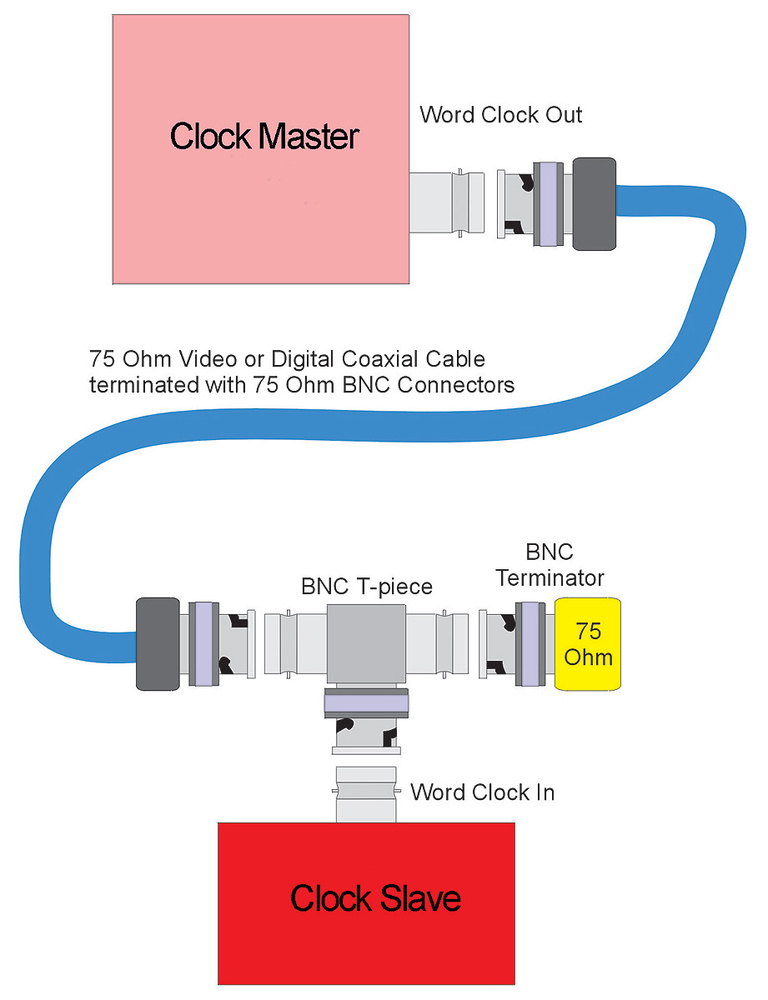 It's also critically important to terminate word clock signals correctly. The word clock input terminal (normally a BNC connector) on some devices is deliberately unterminated (high impedance), while some are permanently terminated and others are switchable. If the line is unterminated, the clock signal will be reflected back down the cable, which could prevent some devices from detecting and locking onto the word clock information. The usual way to apply a termination in these cases (as shown by the diagram, left) is to fit a BNC T‑piece to the word clock input terminal, attach the clock cable to one side and a 75Ω termination plug to the other. Double terminations (where an extra termination is added inadvertently to one already on the line) will result in a low-level signal with the same potential problem.
S/PDIF, AES3 and ADAT interfaces convey the audio data in a 'channel' coding format that also embeds word and bit clocks (and some other useful information). Basically, the signal switches the frequency of a square‑wave signal between 1.5 and 3MHz (for a 44.1kHz sampled signal). So we're talking pretty high‑frequency stuff here — well into video frequency territory, rather than normal audio. Trying to get this kind of signal down a mic cable is difficult because of the relatively high capacitance, which is why specific very low-capacitance 'digital audio cable' is manufactured and recommended for this application. (Other cable types intended for high‑speed data transfer can also work well, particularly Cat5 Ethernet cable).
 The result of sending data down a cable intended for digital data transfer.The two 'eye pattern' graphs above and opposite illustrate the problem. The first shows the result of sending an AES3 signal through 2m of Canford Audio's DFT digital audio cable. What this graph is showing is a series of sections of digital audio data, all overlaid over one another. The top, horizontal blue line represents the high data value (binary 1), and the lower blue line represents the low data value (binary 0). Individual data bits obviously exist only at one of these two levels, and the divisions between one data bit and the next are represented by the vertical blue lines.
As you can see, with this digital audio cable the source signal is being received still looking very square and clean, and each individual 'bit cell' (also referred to as the 'eye' pattern) is clearly identifiable and very 'open.' The small red rectangles within each bit cell represents the minimum eye pattern area that must be kept clear for the receiver to be able to interpret the data reliably — in effect, this is the 'decision zone', where the receiver has to decide whether the data is high or low for that specific data bit.
The second graph  Similar results when using standard mic cable of the same length.shows exactly the same thing, but this time with the signal passing through 2m of standard professional star‑quad microphone cable. The rising and falling edges between each bit cell have obviously been slowed down dramatically, and follow a ragged curve rather than the crisp up or down switching seen in the DFT cable. This is due entirely to the capacitance of the cable storing, and then releasing over time, the electrical energy from each change of signal voltage. While the damage is very obvious, it's still not disastrous and the data can still be received reliably — but you can certainly see how the eye pattern is starting to 'close up'. Now imagine what would happen if you tried to send a signal down many tens of metres of mic cable! In practice, it would become unrecoverable after about 15 to 25m.
 With S/PDIF and AES formats, clock jitter is directly affected by the audio data content to some degree, because of the different cable‑capacitance charging and discharging times that occur.The critical aspect of this waveform damage is that the rising and falling edges of each bit cell are used to define the bit‑clock transitions, and the distortions caused by cable capacitance can therefore introduce clock jitter. The diagram above shows how the data is conveyed in the S/PDIF and AES3 interface formats. The audio data ones are conveyed by switching the signal between high and low (or vice versa) mid‑way through the bit period (ie. sending the 3MHz square wave), while audio data zeros are conveyed by remaining at a constant level for the entire bit period (sending the 1.5MHz square wave). This arrangement is actually very similar to the way standard linear timecode works — although that system operates by switching between 1kHz and 2kHz signals, giving rise to the characteristic warble. This kind of channel code arrangement (often called a Bi‑Phase Mark Code) has the advantage that the recovered data is not affected by the overall signal polarity — all that matters is whether the signal transitions midway through a bit cell period or not, rather than whether it is a high or low voltage at any particularly time. However, as the diagram shows, the amount of clock jitter is directly affected by the audio data content to some degree, because of the different cable‑capacitance charging and discharging times that occur.
Ideally, the receiving circuitry will be able to remove this interface jitter, but not all devices manage this equally well (as shown in the investigations into A‑D converter clock‑recovery above), and if the embedded clocks are to be used as a clock reference (as is common practice in D‑A converters, for example), then this interface jitter can become part of the overall system's clock jitter, potentially resulting in reduced D‑A (or A‑D) performance.
The Clocks On Test
ANTELOPE AUDIO
Isochrone Trinity £2985$3995
An immensely powerful and versatile device which is easy to use and caters for all eventualities. internal oven included as standard; two word clock inputs, AES11 and S/PDIF inputs, and BNC input for 10M (see below); nine independent sets of outputs, each operable at different sample rates; Channel A gives six word clock outs, two each of AES, S/PDIF, and 'x256' outs; Channels B & C offer four word clock, one AES11 and one S/PDIF outs; three separate HD video feeds, each with two outputs; three SD video reference outs; remote control software via USB; supports varispeed clocks; caters for standard video industry pull‑up/down rates for NTSC and film transfers.
Isochrone 10M £5340$6495
The 10M, pictured below left, is an external reference clock for Antelope's Trinity and OSX master clocks, and is based on a rubidium atomic clock. It is claimed to be accurate to 0.03PPB (parts per billion), with long‑term stability of 2PPB. It takes about 10 minutes to reach the optimum operating temperature and is intended to be left running continuously. Mains & battery power; eight buffered 10MHz BNC outputs.
Antelope Audio +44 (0)20 8133 8113+1 415 869 9661.
APOGEE
Big Ben £1232$1340![]()

The Big Ben is intuitive to operate and has a flexible feature set that covers most situations well: six BNC, optical and coaxial S/PDIF and ADAT outs, word clock outs, and two AES11 outs; optional X‑card for video of Firewire interfaces; 'Adaptive Loop Filtering' removes jitter from external reference signals; two AES11 inputs, optical & coaxial S/PDIF and ADAT inputs, word clock input (accepts SD video); switchable 'Sure Lock' function provides seamless backup when external reference is lost; audio references can be routed to all audio‑capable outputs by default (this option can be disabled); standard sample rates from 44.1 to 192kHz; last two word clock outs' sample rates can be multiplied (x256, x4, x2, x1, x0.5, or x0.25); termination state of connected cables is indicated (over-terminated, correct digits 75Ω, and unterminated).
Apogee +1 310 584 9394.
AUDIO & DESIGN READING
SynchroGenius HD Pro £1520$3063![]()
![]() This cost‑effective unit is simple and intuitive to configure, but is deceptively powerful and versatile, and ideal for any video‑related audio application: external reference inputs include AES11, word clock, 1, 2, 5 & 10MHz GPS satellite clocks, HD & SD video, linear timecode (standard 24‑30fps frame rates); optional crystal oven and dual‑redundant mains supply; output sample rates from 44.1 to 192kHz; four AES11 outs, six word clock outs (two of which offer 2x or 4x multiplication), three SD and the HD tri‑level video outs; 'Softlock' facility ensures continuous output when input reference fails; HD outputs support full complement of frame rates and video formats; video pull‑up/down rates provided on digital audio clock outs; three user memories; and front‑panel lock‑out switch.
This cost‑effective unit is simple and intuitive to configure, but is deceptively powerful and versatile, and ideal for any video‑related audio application: external reference inputs include AES11, word clock, 1, 2, 5 & 10MHz GPS satellite clocks, HD & SD video, linear timecode (standard 24‑30fps frame rates); optional crystal oven and dual‑redundant mains supply; output sample rates from 44.1 to 192kHz; four AES11 outs, six word clock outs (two of which offer 2x or 4x multiplication), three SD and the HD tri‑level video outs; 'Softlock' facility ensures continuous output when input reference fails; HD outputs support full complement of frame rates and video formats; video pull‑up/down rates provided on digital audio clock outs; three user memories; and front‑panel lock‑out switch.
Independent Audio +1 207 773 2424.
www.independentaudio.com www.proaudio.uk.com
DRAWMER
MClock Lite £680$1055![]()
![]()
The MClock Lite is simple, but more than adequate for many digital audio setups: 10 word clock outputs (eight on rear, two on front); internal crystal clock (44.1 to 384kHz), or external word clock reference distribution unit (no jitter reduction or attempts to sync when running on external clock).
MClock Plus £1140$1725![]()
![]() The MClock Plus has no video‑sync capability, but it is very comprehensively equipped for digital audio applications: uniquely includes two sample‑rate converters (SRCs) making interfacing temporary or non‑sync'able equipment straightforward; 10 word clock outs (eight on rear, two on front); four AES11 outs (two on XLR, two on phono); AES11 and BNC word clock inputs; SRCs have AES, S/PDIF and TOSlink outputs, and selectable inputs, with AES3, S/PDIF and optical options; proper dithering from 24 to 16‑bit word length; can display sample rate with its relative error.
The MClock Plus has no video‑sync capability, but it is very comprehensively equipped for digital audio applications: uniquely includes two sample‑rate converters (SRCs) making interfacing temporary or non‑sync'able equipment straightforward; 10 word clock outs (eight on rear, two on front); four AES11 outs (two on XLR, two on phono); AES11 and BNC word clock inputs; SRCs have AES, S/PDIF and TOSlink outputs, and selectable inputs, with AES3, S/PDIF and optical options; proper dithering from 24 to 16‑bit word length; can display sample rate with its relative error.
Transaudio Group +1 702 365 5155.
MUTEC
iClock £1169$1475
Reviewed in SOS October 2005, the iCLock is impressively versatile and powerful, perfectly suited for any audio‑for‑video application: two BNC reference inputs can auto‑detect a variety of sources, including word clock (36 standard rates from 8kHz to 24.5MHz, including x256 Superclock, DSD64, DSD128 and DXD clocks (for use in SACD applications), HD tri‑level, and SD video, AES3id and S/PDIF (32‑192kHz), GPS 1, 2.5, 5 and 10MHz clocks, 1.024 and 2.048 Telecomms clocks, and DCF77 and MSF60 broadcast radio clocks); AES11 input accepts 32‑192kHz signals; four SD video outs (HD reference can be distributed via these); optional video‑sync generator; eight word clock outs, switchable in pairs (word clock at sample‑rate multiples, x256 Superclock, and standard video frame‑rate); two pairs of AES11 outs; one pair of S/PDIF outs; standard pull up/down options caterred for; ±20 percent varispeed; switching hierachy for the three reference inputs provides two backups in the event of reference signal failure.
Mutec +49 30 746 8800.
www.iclock-net.de www.mutec‑net.de
ROSENDAHL
Nanoclock £1061$1300![]()
![]()
The Nanoclock is a relatively simple master clock, with broadly similar functionality to the Drawmer MClock Lite: 12 BNC word clock outs, four of which switchable to x256 'Superclock'; two BNC transformer‑isolated reference inputs, one capable of accepting 32‑100kHz and the other 32‑200kHz clock signals; three operating modes — 'Distributor' (two inputs routable separately to 12 outputs), 'Generator' (outputs configured individually for different multiples of internal sample rate), and 'Failsafe' (variation on 'Distributor' to overcome problems in the event one of the reference signals fails).
Rosendahl +49 (0)8806 957480.
www.rosendahl‑studiotechnik.de
Prices include VAT.