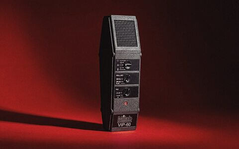
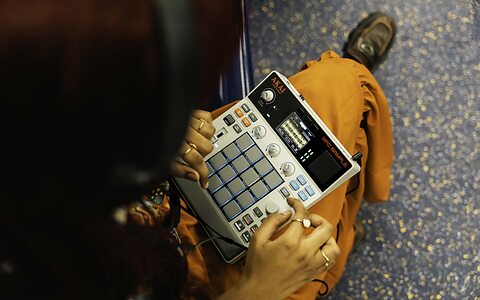
Sound Shadow
The area behind an acoustic baffle on the opposite side from the sound source where the sound level is greatly reduced due to sound diffracting around the baffle.
To find the exact phrase, put the words in quotes or join them together with a plus sign e.g. live+recording or "live recording".
To find, say, all live recording articles that mention Avid, enter: live+recording +avid - and use sidebar filters to narrow down searches further.
The area behind an acoustic baffle on the opposite side from the sound source where the sound level is greatly reduced due to sound diffracting around the baffle.
A signal processing technique first conceived by Alan Blumlein to correct for spatial imaging anomalies inherent in stereo microphone arrays and loudspeaker monitoring. All shuffling processes involve frequency-dependent adjustments to the width of a stereo signal at different frequencies.
A near-coincident stereo microphone array conceived by the Italian broadcaster Radio Audizioni Italiane (RAI) in the early 1960s. It comprises a pair of cardioid microphones with capsules spaced 21cm apart at a mutual angle of 100°. The resulting SRA is 93 degrees. This technique captures both time and level differences between channels, and is comparable to similar techniques such as NOS, ORTF, DIN, EBS, and others.
A capsule design in which the diaphragm is suspended in open air to detect the difference in relative air pressure on each side of the diaphragm. This design is most sensitive to sound waves arriving directly in front or from behind (the latter with opposite polarity). If the sound source moves above or below the diaphragm the difference in air pressure on each side reduces so the capsule becomes progressively less sensitive, giving a figure-8 polar pattern. The diaphragm mounting is designed to be very compliant at low frequencies to maximise the sensitivity to very small pressure differences. This creates a very strong proximity effect.
The simplest form of microphone capsule in which a diaphragm encloses a chamber of atmospheric air. A passing sound wave causes the diaphragm to move in and out as compressions and rarefactions pass, effectively comparing the air pressure variations of the sound wave with the static ambient air pressure held within the chamber. The diaphragm’s movement is not dependent on the direction of sound waves, merely their passing, so the polar pattern is omni-directional. There is also no proximity effect, and the system remains sensitive to very low frequencies.
An audio meter designed to indicate the phase relationships (correlation) between left and right stereo audio signals. Various meter formats are used, but most are scaled from +1 to -1, with zero at the centre. Full correlation (ie. dual-mono) is shown as +1, while opposite polarity is shown as -1. Fully-wide stereo material (decorrelated) would register around 0. Signals indicated anywhere between +1 and 0 are considered mono-compatible. Dips below 0 towards -1 suggest a listener of the summed mono signal will hear coloured or severely attenuated audio.
The name given to a binaural stereo microphone system developed by Jürg Jecklin but better known as the Jecklin Disc . The Optimal Stereo Signal is often abbreviated to OSS.
M3 is a reference to the attenuation applied to a summed-mono signal, particularly in application to audio metering systems, to maintain electrical headroom and to give a perceived acoustic volume consistent with the stereo source. M3 uses a 3dB attenuation ((A+B) – 3dB ) and is most appropriate where the stereo source comprises largely decorrelated signals (ie. normal stereo).
M6 is a reference to the attenuation applied to a summed-mono signal to maintain electrical headroom and to give equivalent metering levels with the stereo source. M6 uses a 6dB attenuation ((A+B) – 6dB ) and is most appropriate where the stereo source has largely correlated signals (ie. dual-mono).
See Goniometer
A two-dimensional visual pattern produced by the interaction of two independent signals, each controlling the amplitude of one display axis. Used in the Stereo Goniometer and Stereo Vectorscope
The difference in loudness or intensity of a sound wave reaching the left and right ears. In real life this is caused by diffraction of sound around the head at high-frequencies (above about 700Hz), causing a 'sound shadow' for the more distant ear. The brain uses the inter-aural level difference as a means of identifying the location of a sound source which will be louder on the side of the closer ear. See also ITD
The difference in the arrival time of a sound wave reaching the left and right ears. In real life this is caused by the extra distance the sound wave has to travel around the head, resulting in a detectable phase shift for frequencies below about 700Hz. The brain uses the inter-aural time difference as a means of identifying the location of a sound source which will be earlier on the side of the closer ear. See also ILD
A stereo microphone device used primarily for capturing binaural stereo and a variation on the OSS technique. Similar to the Jecklin disc, the Schneider disc comprises a circular baffle of 30cm diameter with acoustic absorption material on both surfaces supplemented with a 12cm foam-covered sphere at the centre of the disc to better approximate the acoustic characteristics of the human head. Omni-directional microphones are placed on either side with a roughly 16.5cm spacing and angled outwards at 20 degrees.
The name given by Alan Blumlein to a stereo signal comprising only amplitude differences between the two channels. It can be created by using a pan–pot in a mixing console, or with a coincident (X-Y) microphones.
A stereo microphone array designed to extract the most attractive qualities associated with both spaced-omni (A-B) and coincident (X-Y) arrays. Inter-channel level differences are captured by angling directional microphones outwards, and inter-channel time differences are obtained by spacing the microphone capsules apart. In practice, some of the imaging accuracy associated with coincident techniques is sacrificed for the much greater sense of spaciousness associated with spaced-omni techniques. Popular hybrid arrays include ORTF, NOS, DIN, EBS, RAI and Gerzon.
An effect where the stereo sound appears to ‘puddle’ near the two loudspeakers without creating a continuous soundstage between them. It commonly occurs if microphones in a stereo array are spaced too far apart.
(HRTFs) Parameters which describe a unique set of acoustic filters created by sound reflections from an individual’s head, shoulders, and pinnae which modify the sound waves entering the ear canal. These unique characteristics are learned to allow the brain to locate sound sources in the 3D space around the listener. Perceiving accurate sound placement from a binaural audio source relies very heavily on the material being processed accurately with an individual’s personal HRTFs.
A stereo audio vectorscope which displays the stereo sound image as a Lissajous Figure to assess the correlation and stereo width between channels, as revealed by the phase and amplitude relationships between the two channels.
The two audio channels are plotted on diagonal axes such that a left-only signal is shown as a diagonal line from top-left to bottom-right, while a right-only signal runs from top-right to bottom-left. An identical signal on both channels (dual-mono) results in a thin vertical line, while identical signals in opposite polarity create a thin horizontal line. Normal stereo creates the appearance of a circular tangled ‘ball of string’.