Pulse-width modulation is a vital tool in achieving lush-sounding synthesized string pads — so what if your synth doesn't have it? Fear not — for PWM can itself be synthesized. Here's how...
 Photo: Richard EcclestoneLast month, we started investigating how to synthesize strings, and the wonderful lush string sounds produced by the dedicated analogue ensemble keyboards of the 1970s. In doing so, we found that the chorusing of two slightly detuned and/or modulated oscillators was an important part of their sound; one that we could emulate using pulse-width modulation (or PWM).
During this investigation, I made a couple of statements about the nature of PWM and the audible effect it has on a previously static pulse waveform. Without any kind of proof, I asked you to accept that pulse waves whose widths are modulated by triangle waves have an interesting and largely unknown characteristic; they exhibit two pitches, one of which undergoes pitch modulation that oscillates at the PWM rate above and below the true oscillator pitch. I said I'd return to this point this month, and I will, because it will allow us to come full circle and produce some amazing ensemble sounds on synths that you might think incapable of generating them.
It is, in fact, relatively simple to create a close approximation of a pulse-width-modulated sound, even on a synth that doesn't offer PWM. By way of proof, this month I'll take one of the most 'digital-sounding' of all the synth engines derided by vintage-synth anoraks — the 'AI' synthesis used in Korg's famous M1 workstation — and create a sound that is truly 'analogue' in warmth and character.
If you wish to know some of the theory behind the method that makes this possible, take a look at the box on the nature of the pulse waveform, and then at the larger box on analysing PWM. If you're not bothered about the theory, you'll simply have to accept that when they're combined in the right way, the 'staircase' waveforms shown in Figure Z at the end of the large box form the perfect pulse-width-modulated pulse wave. It's from this point that we'll now begin.
PWM From Combined Waveforms
 Figure 1: Trying to recreate PWM using two square waves.As explained in the box, the two staircase waves that comprise PWM extend to infinity, so it's clear that no analogue synth can generate them. This is because they would require internal voltages whizzing off towards infinity and minus infinity (and I don't know how you feel about having infinite voltages floating around inside your synth, but I would rather avoid it). The situation is no better if we turn to digital synthesis. Instead of infinite voltages, we need infinite wordlengths. This might lead you to believe that it's impossible to generate the PWM waveform without access to PWM itself, but fortunately, this is not the case.
 Figure 2: An idealised representation of the signal generated by the architecture in Figure 1.Given the nature of PWM and the 'staircase' waves shown later, it seems reasonable to start any attempt to synthesize PWM using a couple of square-wave oscillators, so we'll adopt the architecture shown in Figure 1 (above) to modulate and combine two square waves in the way that we know characterises pulse-width modulation. Unfortunately, we obtain the waveform shown in Figure 2. It's an interesting wave, with a sort of 'double PWM' above and below its central amplitude. What's more, it exhibits a pleasing chorused quality, but it's audibly not PWM, and I'd like us to get closer to the ideal. If you have a basic synth and an oscilloscope, you could try combining sawtooth waves, or even square and sawtooth waves, but the results are no better. However, if you have one of the few instruments that offer sawtooth and ramp waves, you could try combining these. I used analogue modules present in my Analogue Systems Sorceror modular synth — two RS90 oscillators (which offer sawtooth and ramp waveforms), an RS380 modulation controller, and an RS160 mixer, to be precise. Bingo! When patched and programmed correctly, the result looks just like PWM, as shown in Figure 3.
 Figure 3: Emulating PWM with modulated sawtooth and ramp waves.Note that Figure 3 shows a low-frequency amplitude modulation at the LFO speed (hence the downward and upward slope to the resulting PWM wave). Don't worry about this; the prominence of the modulation in the diagram is a consequence of the limited space available for the drawing. If the audio waves are pitched at a few hundred Hertz (somewhere in the middle of the piano keyboard) and modulated by an LFO running at a fraction of a Hertz, this modulation is of no significance, provided that you allow sufficient headroom to accommodate it. If you want, you can use a high-pass filter to remove it, but it's rarely worth the effort.
Creating PWM... Without PWM
Although it's not strictly kosher to do so, I am now going to take advantage of a trick that will allow us to emulate the PWM sound on synths less complex than the Sorceror. In isolation, the audible difference between a sawtooth wave and a ramp wave is, well... inaudible. This is because they are static waves that have the same spectrum; there is merely a change of polarity. There are times when this difference can be significant, but it is of little consequence at others. Luckily, the two oscillators generating the waves in Figure 3 are never of the same frequency, so this is one of those occasions when you can use a sawtooth to replace a ramp wave with no audible effect. This, of course, is a good thing, as many more synths offer sawtooth waves than ramp waves. In other words, you can mix two simple sawtooth oscillators, and, if one is frequency-modulated slightly with respect to the other, you will obtain a sound that is all but identical to that of a single, pulse-width modulated, pulse-wave oscillator. Sure, the waveform looks different, but the sound is the same.
Knowing this, we can now create PWM 'string' pads on a synth that has no PWM. As promised, to illustrate this, I have taken the Korg AI engine, as found in Korg's M1 and 'T'-series, and programmed something that is warm and, dare I say it, quite 'analogue' in nature. Given that the M1 is often criticised for being 'soulless and digital' (whatever that means) this was deliberate; after all, if we can use the analyses in the boxes in this article to achieve a convincing imitation of a string ensemble using AI, the theoretical principles must have real practical value.
To begin, I took my Korg T2, which is an M1 with a longer keyboard and a decent screen, and programmed the oscillator parameters as shown in Table 1, below.
Table 1: Korg T2 Oscillator Parameters
|
I then moved on to the twin filters (one for each oscillator) and set the cutoff of each to '75', with a little keyboard tracking. All other filter parameters remained at zero. These settings emulate the limited bandwidth and simple filtering on the original string synths.
Moving on to the T2's twin amplifiers, I defined each with a trapezoid envelope exhibiting a rapid but smooth attack, and a gentle release (Table 2).
Table 2: Korg T2 Aamplifier/Contour Parameters
|
The only subtle parameter I used was keyboard tracking. With a negative value, this weights the loudness of the sound to the bottom end of the keyboard, thus generating additional warmth. I set all the other parameters on this page to zero.
The next page contains the Modulation parameters and, ignoring things such as pitch-bend and aftertouch, it was here that I defined the pitch modulation of Oscillator 2. The relevant parameters are in Table 3 below.
Table 3: Korg T2 Modulation Parameters
|
And that's all there is to it. If you have access to an M1 or a 'T' -series synth, you'll find that it's definitely a PWM-type sound, despite being created on an instrument that does not offer PWM. Sure, the result still lacks a little of the warmth of, say, the PWM found on a Roland Juno 60, but not to worry... we can improve the patch considerably by detuning Oscillator 2 by a value of '10', or thereabouts (the eighth parameter in Table 1). This is something that you cannot do on a Juno!
Of course, there's nothing stopping you using the Korg's onboard effects to thicken the sound still further. Careful use of EQ allows you to shape the sound, and the addition of chorus and a splash of reverb leaves me in no doubt that I could fool you into thinking that my T2 is a vintage ensemble keyboard, and not a digital workstation. This should not be surprising; most string synths relied heavily on built-in chorus effects to thicken a weedy initial timbre. In contrast, what we're doing here is adding chorus to a basic tone that already has many of the characteristics we want, and sounds superb.
Table 4: Super JX10 Parameters
|
More On Strings & Layering
A few months ago, I showed that you can create excellent sounds by layering patches to create a more interesting composite. The T2 is capable of this, and it's simple to create two similar versions of the PWM patch, mixing them and passing them through the effects to create an even deeper and more involving sound. You could even use three patches, tuning these to 16', 8' and 4', and mixing them as desired to emulate the Cello, Viola and Violin options offered by some of the better vintage ensembles. Admittedly, the polyphony drops to eight voices (two layers) or five voices (three layers) but the resulting sounds are so lush that I doubt you would want more.
Fortunately, layering is not a facility limited to digital synths and workstations. Just as we recently superimposed 'Piano 1-A' and 'Piano 1-B' to create an acoustic piano patch on the Roland Super JX10 (see the instalment of this series in SOS January 2003), we can use the same principle to create some of the world's best string pads.
Selecting the JX10's 'Whole' mode, we'll start by programming the first Patch in a Performance, setting DCO1 and DCO2 to the values shown in Table 4. As you can see, both oscillators are producing sawtooth waves, with DCO2 detuned by four cents compared with DCO1. And, as on the Korg T2 example of a moment ago, we add a smidgen of 'square' pitch modulation to create the PWM effect.
The initial sound then passes through the filters and the VCA. The parameters in Table 5 conform to the concepts described over the past couple of months, with all the JX10's 'modern' facilities switched off... this Patch requires only the facilities found on basic analogue synths.
So, how does it sound? Remarkably, given the low second-hand price of a JX10, this Patch is much nicer than the ensemble sound I created last month on the much more expensive Jupiter 6. In my opinion, it's smoother, stringier and much more useable in a mix.
Table 5: Super JX10 Filter, VCA & Envelope Parameters
|
But we need not stop there. Remember that although the Jupiter 6 offers just two oscillators per note, and Freeman's original String Synthesiser (which is where this discussion began) had three, we can now go further by taking advantage of the JX10's Dual Mode; its ability to layer two sounds in a Performance. I'll leave it to you to design the precise nature of the second Patch... but you should consider each of the following changes.
- Changing the LFO speed and depth alters the perceived PWM effect, and when combined with the first Patch, this enriches the sound by ensuring that the ear cannot detect any obvious periodic modulation.
- Altering the relative pitches of DCO1 and DCO2 changes the depth of the chorus effect.
- Adjusting the filter cutoff and envelope settings slightly will enrich the sound, because the ear will be aware that there is something more complex than a single sound at work, although it still won't be capable of separating the Patches from one another.
Having programmed the second Patch, you can now mix this with the first. Take advantage of the JX10's ability to detune Patches against one another, add a bit of external reverb and... Wow! The results can be gorgeous; rich, involving, and with impressive depth. What's more, we still haven't even taken advantage of the JX10's two built-in chorus units! Every note you hear is simply four detuned and modulated oscillators shaped by two low-pass filters and a pair of VCAs.
But now it's time to create our ultimate ensemble sound... just change parameter 64 from 'OFF' to '1' in both Patches to apply chorus to each. You'll find that the resulting sound is far better than what you can coax from the majority of string machines.
Epilogue
So there we have it... we've created superb vintage-style 'string' and 'ensemble' sounds on two unlikely instruments; one a hybrid analogue/digital synth with DCOs, and the other an entirely digital synth with nary a voltage-controlled wotsit in sight. Neither offers PWM, but both can sound as rich, lush, and warm as many more highly rated (and considerably more expensive) instruments.
In short, if you're thinking of shelling out several hundred pounds on some unjustifiably revered string synth... stop. Don't be a fashion victim! My advice would be to learn how to program a JX10, and save yourself a few hundred quid.
I would like to thank Dr Christopher Hicks of CEDAR Audio for his invaluable time and patience as he helped me to avoid the unintentional application of signal-processing theory egg to my face.
The Nature Of The Pulse Waveform
What is a Pulse wave? We all know what one looks like (you can see several in the larger box over the page if you need a reminder), but how can we break it down further? One way is to look at its harmonic content, as we did right back at the very start of this series, when we considered the various waveforms found on common analogue synths. To refresh your memories about how to describe static waveforms in this way, let's first look at the harmonic content of a sawtooth waveform.
If you've been following this series, you'll probably remember that the sawtooth wave has every harmonic present, with the amplitude of a given harmonic 'n' equal to 1/n times the amplitude of the fundamental. Figures A(i) and A(ii) below show this wave and its spectrum.
Note that rather than draw idealised representations, I have calculated all the waveforms and spectra shown here using 120 harmonics. If the fundamental were, say, 200Hz (a little below middle 'C') the highest harmonic would lie at 24kHz, which is well above the bandwidth of most synths (and your ears).
Now let's move on to the square wave. Although the shape of this is quite distinct from the sawtooth, its spectrum is similar — in fact, it appears to be the same, except that every even-numbered harmonic is missing. See Figures B(i) and B(ii) below.
As has been pointed out many times before, the square wave is simply a special case of the general family of pulse waves, distinguished only by the fact that the wave spends the same amount of time at the top of its cycle as it does at the bottom. We refer to this ratio as the 'duty cycle' of the pulse wave, and since the square wave spends 50 percent of its time at 'the top', we say that it has a duty cycle of 50 percent. Of course, there's nothing stopping us from creating pulse waves with other duty cycles, from 0 percent (where the wave spends none of its time 'at the top', and is therefore a silent DC signal at the minimum voltage) to 100 percent (where it is another silent DC signal, but this time at the peak voltage). Many synths allow you to program the pulse width in a range that lies typically between 5 and 95 percent. Others, such as the Minimoog, offer a number of fixed options. Either way, these produce a huge range of tones that are vital for imitating instruments as diverse as woodwind and bass guitars.
So let's now look at the waveform and harmonic content of other pulse waves, and in so doing correct a long-standing mistake usually made in discussions of pulse waveforms. It is often said that the harmonic spectrum of a pulse wave with a duty cycle of 33.3 percent is the same as that of the sawtooth wave, but with every third harmonic missing, and that the spectrum of a pulse wave with a duty cycle of 25 percent is the same as that of the sawtooth, but with every fourth harmonic missing... and so on. However, this is not the case, as we will now see.
Figure C(i) below shows a pulse wave with a duty cycle of 33.3 percent, and Figure C(ii) shows its spectrum. As you can see, this does appear to be the same as the spectrum of the sawtooth wave, but with every third harmonic missing... so where's the mistake?
Well... Figure D(i) below shows a pulse wave with a duty cycle of 25 percent, and Figure D(ii) shows its spectrum. Now you can see the difference. True, every fourth harmonic is missing, but the amplitudes of the others no longer exhibit the 1/n relationship. This becomes increasingly apparent as the duty cycle becomes narrower; if you're in any doubt, take a look at the spectrum for a pulse wave with a duty cycle of one-twelfth (8.33 percent) shown in Figure E (right).
The pulse wave's spectrum is defined by something called a 'sinc' function. This has nothing to do with synchronisation, or domestic water basins with plugs at the bottom, for that matter. Sinc is a mathematical function described by the simple equation shown in the top right of Figure F (below right). Without investigating this any further, it's enough to understand that the amplitude of any pulse-wave harmonic is defined by the value of the sinc function at that point (see Figure G below). Of course, you can't have negative amplitudes (or not for the purposes of this discussion, anyway), so we take the absolute value of each amplitude shown in Figure G, and thus we obtain Figure E again.
Looking more closely at these diagrams, it's clear that there can be no harmonics at the points where the sinc function crosses the 'X' axis, which explains why a pulse wave's missing harmonics are evenly spaced. It also explains why most people's attempts to create pulse waves using additive synthesis are doomed to failure. I have illustrated this by generating a 33.3 percent pulse wave as 'a sawtooth spectrum with holes in it'. As you can see, the spectrum in Figure H(ii) below may look no different from that in Figure C(ii), but its waveform, shown in Figure H(i) below, is a repeating 'staircase', with the number of steps equal to the spacing between missing harmonics. Remove every third harmonic (as illustrated) and you get three 'steps' in the staircase; remove every fourth, and you get four steps... and so on. If you removed every hundredth, accepted wisdom would suggest that you would obtain a narrow pulse wave (ie. with a duty cycle of one percent) but in reality, you obtain a staircase with one hundred small steps, which, if you think about it, is all but indistinguishable from a sawtooth wave. Given their nearly identical spectra, this is hardly surprising!
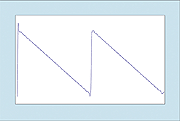 Figure A(i): The sawtooth wave. Figure A(i): The sawtooth wave. |  Figure B(i): A 'real' square wave. Figure B(i): A 'real' square wave. |  Figure C(i): A pulse wave with duty cycle of 33.3 percent. Figure C(i): A pulse wave with duty cycle of 33.3 percent. |
 Figure A(ii): The harmonics that produced the wave in Figure A(i). Figure A(ii): The harmonics that produced the wave in Figure A(i). |  Figure B(ii): The harmonics that produced the wave in Figure B(i). Figure B(ii): The harmonics that produced the wave in Figure B(i). | 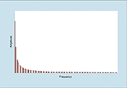 Figure C(ii): The harmonics that produced the wave in Figure C(i). Figure C(ii): The harmonics that produced the wave in Figure C(i). |
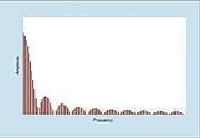 Figure E: The harmonics that produce a pulse wave with a duty cycle of 8.33 percent. Figure E: The harmonics that produce a pulse wave with a duty cycle of 8.33 percent. | ||
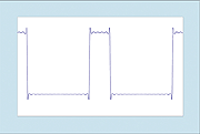 Figure D(i): A pulse wave with duty cycle of 25 percent. Figure D(i): A pulse wave with duty cycle of 25 percent. | 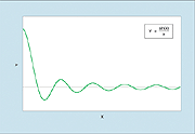 Figure F: The sinc function. Figure F: The sinc function. |  Figure H(i): The waveform generated by the spectrum in Figure H(ii). Figure H(i): The waveform generated by the spectrum in Figure H(ii). |
 Figure D(ii): The harmonics that produced the wave in figure D(i). Figure D(ii): The harmonics that produced the wave in figure D(i). |  Figure G: How the sinc function determines the amplitudes of pulse waves' harmonics. Figure G: How the sinc function determines the amplitudes of pulse waves' harmonics. |  Figure H(ii): A 1/n spectrum with every third harmonic missing. Figure H(ii): A 1/n spectrum with every third harmonic missing. |
A Different Way Of Looking At PWM
As explained at the start of this article, the effect of PWM can be recreated even on synths that don't offer it. This is made possible by considering PWM as the product of two pitches. I hinted at this last month, but it's now time to explain it rather more thoroughly.
Let's start with the square wave shown at the top of Figure Q below. As you can see, the waveform is static — in other words, the waves' shapes do not change as time passes. But this need not be the case — there are many ways in which we can alter them. We could smooth one or more of the sharp corners off the square wave, make the vertical bits slope (creating a trapezoid waveform), put some wiggles in the horizontal bits, or create combinations of these... and so on. Sure, the resulting waveforms might be difficult or even impossible to generate using analogue electronics, but they are nonetheless valid, and an appropriately programmed digital synth should be able to generate any of them with ease. Nevertheless, one modification to the wave shape of a pulse wave that many analogue synths can perform is modulation of the duty cycle.
Looking now at all of Figure Q, you can see a second, low-frequency modulating waveform shown in green underneath the square wave. I have chosen a triangle wave for the low-frequency modulator, because this will best demonstrate the principles that I wish to describe.
Let's imagine that when the modulator is at its minimum voltage, the duty cycle of the audio wave is very close to 0 percent. This means that the first pulse shown in the audio waveform has almost zero duration. As the modulator increases in voltage, the duty cycle increases until, when it reaches its maximum, the next pulse has a duty cycle of virtually 100 percent. As the modulation voltage falls, the duty cycle decreases until the modulator reaches its minimum once more, after which point the whole cycle begins anew. I have shown this as Figure R below.
As we've seen in the box on the nature of the pulse waveform (on the previous page) the duty cycle of a pulse waveform is intimately related to its harmonic content. This means that because the duty cycle in the PWM waveform is constantly changing, so too is the harmonic content of the wave. But, as I stated last month, it is not easy to see why this alone should give PWM its rich, chorused sound. Sure, analysing the harmonic spectrum provides us with a powerful way to describe and understand what's happening to the signal, but it's not necessarily the best way to explain why we hear what we hear. We need to find a better one.
When we consider a signal, there are many ways that we can describe it and analyse it. The most common is the amplitude/time graph, but I've already used a second type this month, the frequency/time graph, which allows us to see how the spectral content of the signal changes in time, and now I'm going to introduce a third, the 'differential' graph, which shows how the gradient of the signal in the amplitude/time graph changes over time. If you're familiar with maths, you'll recognise this concept, but don't worry if you're not, as I'm now going to attempt to differentiate the PWM signal using words to describe the results, with no maths whatsoever. I can do this because of the simple nature of pulse, triangle and sawtooth waves, but it would be almost impossible if we were to attempt this for more complex waveforms.
Let's start at the left-hand edge of the modulated audio signal in Figure R. We're going to scan along it from left to right, and every time we encounter an upward transition in the waveform, we're going to draw an upward arrow at that position. Likewise, every time we encounter a downward transition, we're going to draw a downward arrow.
OK, I'll admit that the first pulse is a bit confusing, because it looks like we should draw a single downward arrow, but this is misleading. This is the pulse with a duty cycle of almost 0 percent, so we must draw both an upward arrow and a downward arrow at that position. Moving to the right, it then becomes obvious that there is an 'up', a 'down', an 'up', another 'down'... and so on, until we come to another pulse where the 'down' and 'up' arrows are almost at the same position (the pulse with a duty cycle of almost 100 percent). This is then followed by a 'down', an 'up', a 'down'... and so on (again) until we reach the next zero-percent pulse. If you study Figure S (above), you can see that — although it's a bit complex to describe in words — what we've done is visually very clear and intuitive.
I'm now going to split Figure S into two separate graphs: one that comprises the first half of the lower part of Figure S, in which the down arrows are more widely spaced than the up arrows; and the other comprising the second half, in which the converse is true (see Figures T and V, right and above right). If you refer back to Figures Q and R, you can see that these two new graphs are, respectively, the regions in time during which the modulating signal is rising, and when it is falling.
Now comes the bit that is somewhat less than intuitive... Despite the fact that they are derived from a single waveform, we can treat the 'up' arrows in Figure T as a single signal, and the 'down' arrows as a second, independent signal. We can do this because the sizes of the arrows remain constant. What's more, because the spacing of the arrows comprising each signal is also constant, we can infer that the frequencies of these signals are also constant — for the duration represented by Figure T, at any rate. At this point, we have no idea what the shapes of the separate 'up' and 'down' signals might be. What we do know, however, is that the 'up' signal completes nine cycles (the red arrows) in the same time that the 'down' signal completes eight cycles. We can therefore state with confidence that there are two audio signals present, each of constant frequency, but with one lying at nine-eighths of the frequency of the other. I have shown this as Figure U (below left on the previous page).
Looking now at the part of the PWM wave generated when the modulator is falling (see Figure V, above left), we see that there are seven complete 'up' cycles for every eight 'down' cycles. We can therefore state that there are again two signals present, with one having a frequency of eight-sevenths of the other. I have drawn this as Figure W (left). Note that this shows how the signal with the higher frequency in Figure U — the red 'up' signal — is the one which has the lower frequency in Figure W.
Next, putting Figures U and W together, I can represent the frequencies of both audio signals in the PWM cycle, as shown in Figure X (below). Note that I have also compressed the timeline by a factor of four to generate Figure X, so that it shows four complete PWM cycles. This helps to bring out the useful factors in this analysis, which are less obvious when viewing just one cycle. Now we can see what is happening... As already stated, in this way of looking at things, the PWM waveform comprises not one, but two independent audio signals, one of constant frequency (the red line that represents the 'up' signal) and one that is undergoing pitch modulation above and below this frequency (the green line that represents the 'down' signal). Figure X also makes it clear why the PWM wave sounds so rich. In having two signal components, the pitch of one of which is frequency-modulated with respect to the other, the PWM wave produced by a single oscillator is no different from the signal produced by two independent oscillators, the pitch of one of which is, umm... frequency-modulated with respect to the other.
But this isn't the end of the matter. We have considered only the case in which the leading edges of the pulses are unaffected by the modulator. In other words, the leading edges (ie. the 'up' signal) are always equally spaced, no matter what else is happening to the waveform. But it is just as valid to consider the case in which both the leading edges and the trailing edges move with respect to the centre of the top of the pulse. If they are affected equally, it doesn't take too much of a leap of faith (or too much graph paper) to realise that the frequencies of both signal components will now be altered, as shown in Figure Y (above).
Now that we have shown PWM to be the sum of two signals, at least one of which is frequency-modulated with respect to the other, it would seem reasonable to speculate that we can recreate it by determining the natures of the 'up' and 'down' signals themselves, and combining them in the correct fashion (mathematically, this combination process is the opposite of differentiation, and is known as integration, but you needn't worry about that if you don't want to). So what about the nature of the 'up' and 'down' signals? Well, imagine drawing the two waveforms you would get by responding independently to the 'up' and 'down' impulses in Figure S (remember that we can treat the 'up' impulses as one signal, and the 'down' impulses as a second, independent signal).
Again, this sounds tricky, but Figure Z (right) should make everything clear. As you can see, we obtain two 'staircase' waves, one ascending to infinity at a rate determined by the gaps between the 'up' arrows, and the other descending to minus infinity as defined by the 'down' arrows. I'll admit that these are not conventional-looking synth waveforms, and they are not cyclic in any traditional sense, but this does not preclude their validity. In fact, if you take a piece of graph paper and add them together, you'll find that you obtain a perfect PWM waveform.
But hang on a moment... If one signal climbs ever on upward, and the other descends downward forever, surely there can be no way for us to construct a true PWM signal using oscillators that do not have the ability to modulate the pulse width directly? After all, synth oscillators simply do not have infinite voltage ranges.
Nevertheless, it can be done — and a look at the main text of this month's article will tell you how.
 Figure Q: A pulse wave with a duty cycle of 50 percent, and a triangle-wave modulator. Figure Q: A pulse wave with a duty cycle of 50 percent, and a triangle-wave modulator. |  Figure R: How a modulator affects a pulse wave to generate PWM. Figure R: How a modulator affects a pulse wave to generate PWM. |  Figure S: Looking at the PWM signal in a different way. Figure S: Looking at the PWM signal in a different way. |
 Figure T: Describing the PWM signal when the modulator is rising. Figure T: Describing the PWM signal when the modulator is rising. |  Figure U: The two signal components that comprise the first part of the PWM wave. Figure U: The two signal components that comprise the first part of the PWM wave. |  Figure V: Describing the PWM signal when the modulator is falling. Figure V: Describing the PWM signal when the modulator is falling. |
 Figure W: The two signal components that comprise the second part of the PWM wave. Figure W: The two signal components that comprise the second part of the PWM wave. |  Figure X: The frequencies of the two components that comprise the PWM waveform. Figure X: The frequencies of the two components that comprise the PWM waveform. | 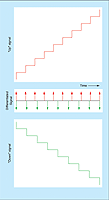 Figure Z: The nature of the separate 'up' and 'down' signals. Figure Z: The nature of the separate 'up' and 'down' signals. |