
Getting the jitters about your digital clocking? Don't know your AES from your EBU? Then read on.
Looking through back issues of Sound On Sound, I discovered that I first wrote about connecting digital equipment some 10 years ago. Not surprisingly, perhaps, little has changed since then in terms of the principles and techniques involved, but some of the interfaces we used then have disappeared now, and the practice of connecting equipment digitally has become a rather more familiar part of our day-to-day lives in the studio.
These days, although there are a few variations on each theme, we really have just two main families of dedicated digital audio interface in common use. These are the AES3 format and the ADAT format. The first is intended primarily for making stereo or two-channel connections, while the ADAT interface can accommodate up to eight channels.
I mentioned several manufacturers' bespoke interface formats in that article 10 years ago, but they have all disappeared from the current scene. Yamaha's Y1 and Y2 formats, Sony's S-DIF and DASH interfaces and Mitsubishi's PD system, for example, are all gone. There are still a couple of manufacturer-specific interface formats around, such as Tascam's T-DIF and Roland's R-Bus, but these are mainly restricted to those specific brands of equipment and are very unlikely to survive another decade.
AES3
Today, easily the most commonly used interface formats are AES3 and its close derivatives. AES3 was introduced as an open standard by the Audio Engineering Society (AES), working with the European Broadcasting Union (EBU), in 1985. It was originally known as the AES-EBU interface but is now more correctly termed AES3 (or IEC-60958 Type I), and it has seen several revisions over the years, the latest being in 2003.
The AES3 specification calls for a 110 Ohm twisted-pair cable with an overall screen, terminated in three-pin XLR connectors. Like conventional analogue audio, the signal flows out of male connectors and into female ones, and the wiring uses the same convention: screen on pin 1 and differential signal on pins 2 and 3. However, unlike balanced analogue audio, the interface is not sensitive to polarity. Instead, a biphase mark code is used in which the binary data content is signified by voltage changes, not the absolute voltage.
The use of XLR cables for AES3 was intended to make the interface familiar and easy to implement, but in hindsight this wasn't a great idea from a technical standpoint. AES3 data is transferred nominally as square waves of up to 7V peak-to-peak with a fundamental frequency of about 1.5MHz. Obviously, the odd harmonics that are crucial to maintaining a square wave shape extend up to 10MHz or so, and this requirement is well beyond the working bandwidth of most microphone cables. So, to work reliably (especially over long distances), the cable construction is critical. In fact, the AES3 specification is designed for transmission over a maximum of 100 metres and, while greater distances are possible with correct cables, ordinary mic cables will often render an AES3 signal unrecoverable after only a few tens of metres.
Of course, properly designed 110 Ohm cables are widely available now for AES3 applications, and you should always use them rather than any old mic cable. However, in many cases a much better engineering approach is to adopt similar arrangements to video technology, since the signal frequencies are very similar. Video interfacing is normally performed using BNC connectors and 75 Ohm (unbalanced) coaxial cables, and cable runs of 1000 metres are easily achievable. So, in 1995 the AES issued an update to the AES3 interface to permit unbalanced connections using BNC connectors and 75Ω cables. Called AES3-id, it has been widely adopted in broadcast and professional circles, particularly by the likes of Sony and Dolby. The signal voltage is typically 1V peak-to-peak, and 1km is given as the maximum expected range.
Reference Clocks
 Two different ways to 'daisy-chain' clocking signals for digital equipment. In larger systems, by far the best approach is to install a separate master clock for the entire system and synchronise all the equipment to it. Master clocks are available with varying degrees of sophistication, but one of the simplest and most versatile is Drawmer's M-Clock (reviewed in SOS March 2003: www.soundonsound.com/sos/ mar03/articles/drawmermclock.asp). At the opposite end of the scale are very powerful devices like Apogee's Big Ben (www.soundonsound.com/sos/ aug05/articles/apogeebigben.htm) and Mutec's iClock (www.soundonsound.com/sos/ oct05/articles/muteciclock.htm).
A simple master clock has a very stable and accurate clock generator providing multiple independent outputs. Typically, these will be either straight word clock feeds on BNC connectors, or AES11 references on XLRs (or sometimes phono sockets). Occasionally you will find a 'Superclock' output too, but this was really only used by legacy Pro Tools hardware.
 A dedicated master clock is a useful way to synchronise complicated digital setups, such as you might find in a large professional studio.Word clock is a simple square-wave signal running at the sample rate, and most devices are equipped to synchronise to an external word clock signal. AES11 is basically a standard AES3 signal which carries an accurate clock reference. Usually the audio sample data carries silence, but sometimes the AES11 signal is used to distribute a line-up tone or some other useful audio signal. An AES11 signal can often be used to synchronise equipment via their inputs if a word clock input isn't provided.
 When working with video, the video syncs and digital word clock must be synchronised to each other. Since timecode counts video frames, it too will then be synchronous with the digital word clock.AES11 is obviously a point-to-point connection: from the master clock to a single device. Ideally, word clock should be used the same way for the most reliable system, but it is possible to 'daisy-chain' word clock connections between several pieces of equipment using BNC T-pieces. This is not a foolproof system (unlike the point-to-point arrangement) and requires a switchable input termination on each piece of equipment. Only the last device in the chain should present a 75 Ohm termination: all the rest must present a very high impedance input to avoid loading the matched-impedance line. If the word clock input termination can't be switched off, you cannot use daisy-chaining.
Some more elaborate master clocks include a video generator, or accept an external video reference signal. This is an important consideration if you are working with digital video, since all digital VTRs require a whole number of audio samples per video frame at the 48kHz sample rate. Consequently, it is essential to ensure that the video frame rate and the digital sample rate are synchronised with each other, and the easiest way to do that is if both reference signals are generated by the same box, or the word clock is itself referenced to a video reference.
S/PDIF
The domestic version of the AES3 interface is known as S/PDIF (Sony/Philips Digital InterFace), and is documented as IEC-60958 Type II. Electrically, this is very similar to the AES3-id format (though it predates it) and requires 75 ohm coaxial cables, terminated in phono (RCA) connectors. The signal voltage is reduced to a nominal 0.5V peak-to-peak and the specifications expect a maximum transmission distance of just 10 metres!
Once again, because very familiar connectors are used there can be a tendency for people to use any old phono-to-phono cable to connect digital equipment. While this may work for short distances, the interface will be considerably less reliable and far more prone to jitter (see below).
There is also an optical fibre-based version of S/PDIF, which is usually named after the company that first introduced it: Toshiba's Toslink. The connector is defined as the JIS F05, and the interface as the EIAJ CP340-optical. In essence, the standard S/PDIF data stream is used to turn a red LED on and off in the transmitter. A light sensor at the receiver detects the light pulses and converts them back to an electrical S/PDIF signal.
Most Toslink 'cables' employ an inexpensive 1mm plastic optical fibre, but there are versions with better-quality fibres, sometimes multi-stranded for greater flexibility. The very best use quartz glass fibres but these are extremely expensive and rather rare, even in loony hi-fi circles. The absence of an electrical connection via a fibre means there can be no ground loops, which is often an advantage. In digital equipment ground loops won't usually produce audible hums, but can cause difficulties in decoding the audio data, with occasional clicks or mutes. Poor-quality fibres behave in a similar way to nasty cables, causing significant deterioration to the digital signal with increased jitter and unreliability.
MADI
The final variation on the AES3 theme, known as MADI (Multi-channel Audio Digital Interface), was intended to provide a simple connection between a digital mixing console and a multi-channel recorder. In 1991, when this interface was first published as AES10, it was designed to convey 56 channels of audio (configured as 28 AES3 pairs) over a single coaxial cable fitted with BNC connectors. However, an enhanced version was introduced in 2003 called Extended MADI or MADI-X, and this provides for 64 channels at 48kHz and 32 at 96kHz. Many implementations provide optical fibre or Cat 5 connectivity instead of the coaxial cable. The fibre interface is particularly useful in live sound and outside broadcast applications where the complete electrical isolation avoids ground loops and potential electrical safety issues. MADI is becoming increasingly common for connecting computer DAWs to consoles, or for linking multiple devices in a machine room to a separate control room using a single cable or fibre. Several manufacturers are now providing MADI interfaces, RME's ADI6432 being one of the most innovative and comprehensive.
A significant difference between MADI and the other AES3-based interfaces is that it does not carry an embedded clock. A separate clocking signal is always required to synchronise the source and destination devices.
Jitter
 Jitter is a term that is often heard, but which few understand. It refers to uncertainty in the timing of a digital signal, and it can arise in various ways. However, it is normally only a problem in the context of A-D and D-A converters.
A poor-quality clock circuit can suffer from jitter if it is unstable, but this is pretty unusual in anything other than the cheapest digital consumer equipment these days. Of more practical relevance is the jitter that is induced in all cables and optical fibres. This comes about because cables inherently suffer capacitance and fibres suffer optical dispersion. In both cases, the effect is to blur the edges of the data pulses so that their timing becomes vague. The longer (or nastier) the cable or fibre, the worse the problem will be.
However, when transferring digital audio between two devices — say, between a recorder and a DAW, or a console and digital reverb — modest amounts of cable jitter have no effect whatever. The AES3 and ADAT interfaces are designed to accommodate a huge amount of timing variation and the jitter would have to be extraordinarily bad to cause any problems.
 These two diagrams illustrate how jitter is introduced into the audio signal, and the impact it can have on the signal.Where jitter does become significant is where the signal is being converted between the analogue and digital domains. Timing variations here will result in samples being measured or reconstructed at the wrong moment in time, and that equates to noise modulation or low-level tonal artefacts, and to stereo image instabilities.
For this reason it is advisable to make your A-D converter the system's clock master. In this way the A-D conversion is controlled by the converter's own clock, which is likely to be very stable and jitter-free. The digital output passed on to a recorder or DAW won't be affected by any cable-induced jitter. If you are using a dedicated external master clock, then either synchronise that to the A-D converter, or use it to clock the A-D converter with the shortest possible cable.
Ideally, a D-A converter should have an external reference clock input to ensure that it can convert the signal from a very stable clock rather than the jittery embedded clock from its input signal. However, very few do. Instead, a very effective solution is to isolate the incoming embedded clock from the conversion clock using a floating buffer or sample!=rate converter. Benchmark have taken this approach with their DAC1 (www.soundonsound.com/sos/jul05/articles/benchmark.htm), for example, and many other manufacturers have sophisticated alternative strategies to isolate the conversion clock from the input's embedded clock.
The AES Data Format
All of these interfaces — AES3, AES3-id, S/PDIF and MADI — carry their audio data in the same basic way. The data is sent serially in separate 'frames', the starting point being identified by a short 'preamble' of a distinct data sequence. It is this preamble which provides the embedded word clock and marks the frame as one in a sequence of 192 (more on that in a moment...).
Every frame contains two sub-frames, each conveying up to 24 bits of audio data plus some housekeeping data. The audio sample is sent with the least significant bit first, and any unused bits are forced to zero. Following the audio sample are four discrete bits called V, U, C and P. The P bit is a simple parity check, used to identify simple malfunctions of the interface connection: there is no error correction facility at all. The V bit indicates 'data validity' and is used to tell a D-A converter whether to convert the sample or mute the output. For example, if the parity check failed, the validity bit would be set to indicate an invalid sample and the D-A would interpolate rather than try to reproduce it.
The User (U) and Channel Status (C) bits are used to convey far more sophisticated programme-related information, but obviously there isn't much you can do with only one bit per audio sample. This is the reason for the 192-frame sequence I mentioned earlier. The Channel status bit transmitted with each sample is stored until all 192 have been collected (making 24 bytes). They can then be decoded and interpreted to provide useful information.
For example, the first byte conveys basics such as the sample rate and whether the data represents linear PCM audio or not. This is important, since the interface can also convey data-reduced formats such as Dolby E in professional circles, and Dolby Digital or DTS data streams in consumer equipment, and these formats have to be decoded before being output. If played out 'raw', the result will sound like full-amplitude white noise, which is obviously undesirable!
Subsequent bytes of Channel status data indicate whether the data represents a single channel or stereo, the sample word length, channel identification in surround-sound applications, the stability of the embedded clock, simple source and destination address codes (four ASCII characters each), a timecode reference, and then some simple error protection data to help protect the channel status bits.
Given the differing requirements, it is not so surprising that there are some discrepancies in the way the Channel status bits have been allocated and have to be interpreted for professional (AES3) and semi-professional (S/PDIF) applications. In the early days this used to cause occasional problems, particularly when working with copyrighted material between professional and consumer equipment. Thankfully, this is rarely a problem these days since most equipment is now sophisticated enough to cope.
The single User bit attached to each audio sample forms a continuous serial data stream. Though this is rarely used in professional applications, it is employed in domestic equipment to convey information like, for example, track numbers and running times from CDs.
High-speed Applications
The AES3 and S/PDIF formats were originally designed to accommodate sample rates up to 48kHz. The subsequent introduction of double sample rates (88.2 and 96 kHz) initially caused problems because the expanded bandwidth requirement exceeded the capabilities of most interface electronics. An early solution was simply to use two AES3 interfaces and two cables, an arrangement often referred to as 'Double Wide'. Instead of each AES3 frame carrying a stereo pair of audio samples, it is used instead to carry two consecutive samples from the same channel, thus accommodating the doubled sample rate. However, a second AES3 interface is then required to carry the second channel.
Although a pragmatic solution, it was inconvenient, and interface electronics quickly improved to operate at twice the speed of the original interface. Thus stereo audio at 88.2 or 96 kHz could be passed over a single AES3 interface, and although this was known initially as a 'Double Fast' interface, it is now the standard way of working with double sample rate material. For quad rates (176 or 192 kHz) the usual way to work at present is an extension of the 'double wide' mode using two single-channel, double-rate interfaces.
A lot of equipment provides multiple outputs these days and, while the 64-channel capability of MADI-X is excessive, most companies offer an eight-channel interface on a 25-pin D-sub connector to provide four parallel AES3 streams in and out. However, there are several differing and incompatible wiring conventions. Tascam implemented an arrangement which has also been adopted by Digidesign and SADiE, and is the nearest we currently have to a 'standard'. Sadly, though, the similar-looking interfaces on Yamaha, Genex and Euphonix equipment are completely incompatible, and in the absence of commercial interface adaptors, bespoke cables are the only practical solution.
ADAT
The ADAT 'Lightpipe' interface was designed for the Alesis Digital Audio Tape machine in 1991, and employs the physical Toslink optical fibre connector but uses a completely different data format from S/PDIF. It was designed to carry up to eight audio channels at 48kHz sample rates, with up to 24 bits per sample, and it has become an immensely popular way of connecting semi-professional equipment.
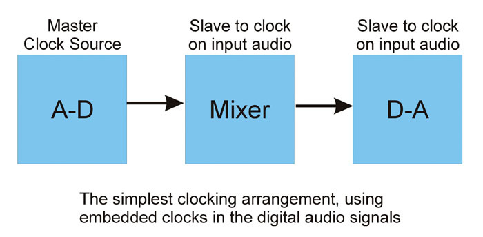

 and external clocking (below left). Some systems, such as ADAT, use an integrated clocking signal. Others may require a word clock connection via the BNC input (above) to ensure all digital equipment works from the same clock. See the box on reference clocks (page 101) for other approaches.") These diagrams show two approaches to digital clocking: simple clocking (above left) and external clocking (below left). Some systems, such as ADAT, use an integrated clocking signal. Others may require a word clock connection via the BNC input (above) to ensure all digital equipment works from the same clock. See the box on reference clocks (page 101) for other approaches.To accommodate higher sample rates, the original Lightpipe format was modified using bit-splitting techniques by a company called Sonorus. S/MUX (short for 'sample multiplexing') basically trades channels for samples. So you can have eight channels at up to 48kHz, but only four channels at up to 96kHz or two channels at up to 192kHz. Most manufacturers implementing ADAT Lightpipe interfaces now support the S/MUX interface extension.
These diagrams show two approaches to digital clocking: simple clocking (above left) and external clocking (below left). Some systems, such as ADAT, use an integrated clocking signal. Others may require a word clock connection via the BNC input (above) to ensure all digital equipment works from the same clock. See the box on reference clocks (page 101) for other approaches.To accommodate higher sample rates, the original Lightpipe format was modified using bit-splitting techniques by a company called Sonorus. S/MUX (short for 'sample multiplexing') basically trades channels for samples. So you can have eight channels at up to 48kHz, but only four channels at up to 96kHz or two channels at up to 192kHz. Most manufacturers implementing ADAT Lightpipe interfaces now support the S/MUX interface extension.
Clocking
Unlike simple analogue interconnections, digital interfacing requires clock synchronisation between source and destination devices. If a digital system is not clocked correctly it will produce, at best, occasional clicks and splats. At worst, the devices will mute completely and refuse to work! In simple terms, the clicks are caused when one device looks for an incoming sample and fails to find one because it is looking at the wrong time.
These clicks can often go completely unnoticed when playing most types of audio material, and I recommend checking a digital system with a test sample whenever you change the clocking arrangements. It only takes half a minute or so to perform the test but it can save serious embarrassment and hours of repeated work — and I say that from personal experience! All that is required is a reliable source of a high-pitched sine wave. A commercial test CD will work fine, though you can create your own test file easily enough: a sine wave of about 4kHz and at about -18dBFS is ideal. If all you can hear is a constant, clean whistle, then all is well with the clocking, However, any clicks indicate a clocking error somewhere.
Simple Synchronisation
With the exception already mentioned of the MADI interface, all of the AES3 interfaces and the ADAT Lightpipe system are self-clocking — that is, they all carry an embedded clock from the source. So, in a simple system, a receiving device can be synchronised just to the embedded clock from the source device. In many cases this happens completely automatically: a D-A converter will automatically synchronise itself to the incoming signal, and a CD recorder will automatically synchronise itself to the digital input when recording, for example.
 Equipment which cannot be synchronised directly must be passed through a sample-rate converter to produce a synchronised output with the clocks of other digital sources.In more complex systems, like DAWs or digital consoles, there is usually a front-panel switch or a software menu to select the required clock source. Typically there will be three options: a digital input, an external word clock (or video) reference, and an internal clock. Which one you choose depends on how the system is configured, but the end result must always be that the device is synchronised with the digital input(s).
The simplest solution is obviously just to select the relevant input as the clock source, relying on its embedded clock. However, if that device is subsequently disconnected or switched off (or changed to a different sample rate) it can leave the system unstable and clock-less. And if you have more than one source to work with at the same time, a more sophisticated solution is required.
Switching to the internal clock ensures that the DAW or console will always be stable and will operate at a known clock rate, but you'll have to make sure that the other digital equipment is now synchronised to it. That means taking a word clock (or some other clocking signal) from the DAW/console and feeding that to the reference clock inputs on the source devices, and switching them to synchronise to the external clock. This is a perfectly valid solution, but can only be used if the source device can be slaved to an external clock — a capability that is absent on a lot of consumer and semi-pro equipment.
If the source can't be synchronised to an external clock you either have to make it the master clock device and slave the DAW/console to it, or use a sample-rate converter (SRC) to make its output appear synchronous. In the latter case, the reference clock from the DAW/console is used to synchronise the output from the SRC while the source device runs independently from its internal clock (the SRC sorts out the difference).
Alternatively...
An alternative approach that shouldn't be overlooked is to abandon digital interfacing completely and hook up the two devices using analogue connections. It always works, it avoids all clocking issues, and with modern converters you'd be hard pressed to hear any difference!