 Some 500‑series racks have parallel I/O on XLR and DB25 connectors, which means you can connect a preamp’s input to both mic and line sources at the same time. But if you engage phantom power on a preamp module, it will appear at both inputs.
I have a 500‑series setup which includes some mic preamps that I’d like to be able to wire up to a jack patchbay for line‑level use, as well as having them available on an XLR bay for the mics. The 500‑series rack has inputs on XLRs and DB25 D‑subs, and I think these are paralleled to make it easy to hook the box up with different cables. So it’s easy physically to connect it to both the line and mic bays. The problem is that when a preamp’s phantom power is switched on it appears on both, and I want the line connection normalled to my audio interface, so that’s not ideal! One solution would be to use an external phantom supply and not use the phantom control on the modules, but that leaves the risk of user error. With that in mind, is there an easy way to block 48V phantom power in a balanced cable (or in a connector) and, importantly, a way that doesn’t have a negative impact on the sound? Is it as simple as soldering a capacitor to one or two of the pins?
Sean Lawton
SOS Technical Editor Hugh Robjohns replies: Transformers will do this, of course, though it’s an expensive option unless you want it to add ‘colour’. There are some commercial phantom blockers too, but again, these don’t come for free!
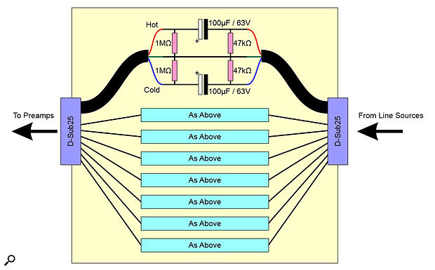
The most affordable DIY solution is to put electrolytic capacitors on the hot and cold lines (positive plate towards the preamp), with 1MΩ and 47kΩ resistors each side to provide the appropriate DC conditions. The resistors should be within 1% or better of the stated value and measured to match pairs as closely as possible — otherwise the CMRR will be compromised and interference may become a problem.
Depending on the patchbay and your soldering skill, it might be possible to wire the components onto the back of the patchbay jacks, but an easy DIY approach would be to build a box with DB25 sockets at either end and plain Veroboard (no copper) in the middle on which you can locate the components. You’d run wires from the sockets’ hot/cold connections to the capacitors on the board, and then on to the other socket, with resistors to individual ground wires.
 A circuit diagram for a simple but effective eight‑channel phantom power blocker.
