Parallel Compression
"Given the difficulty of finding a true upwards compressor,” I hear you respond,”is there an alternative way of achieving something similar?” I'm glad you've asked that, because yes, there is. The idea of parallel compression was conceived to achieve much the same goal as upwards compression. In other words, its aim is to leave the delicate loud transients intact while raising the level of low-level signals — but to do so employing only the standard downward compressors found in conventional studios.
Given that description, you might logically assume that parallel compression somehow achieves a form of upwards compression — and a great many people do, indeed, often refer to it in that way (myself included on occasions). It's all a bit more complicated than that, though, because it really depends on how the parallel compressor is set up. In strict technical terms, a parallel compressor setup is actually a form of downward compressor, but it exhibits a unique and very useful characteristic that allows it to behave exactly like an upwards compressor over a defined dynamic range. Figure 5: The way parallel compression is implemented is conceptually very simple — one merely splits a signal and passes one half through the compressor, and the other half remains uncompressed. The result is then blended together. However, it's also quite common, where resources are available, to run more than one compressor in parallel.
Before we examine real measurements of different parallel-compression configurations, it's probably worth revisiting quickly how parallel compression works. The basic concept is to split the input signal to feed two paths, one being a direct 'through' path, and the other feeding a normal downward compressor. The compressor's output is mixed at unity gain with the direct path to produce the 'parallel compressed' signal.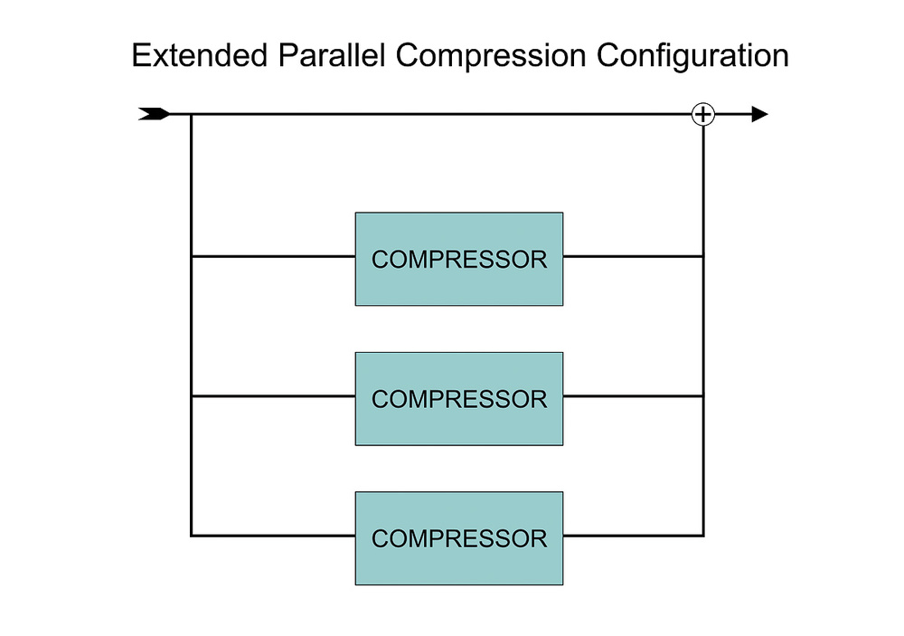
The compressor is set up with a very high ratio — in fact, limiting is often used — and the threshold adjusted so that it provides a lot of gain reduction when the input signal is at its loudest. The more gain reduction the better, in fact: 20dB is a good start, but 40dB would be better! Of course, this requires a compressor that behaves nicely when applying a lot of gain reduction and doesn't generate any distortion products, which some do. The attack and release controls are set to suit the material and the effect required, in the usual way.
When configured for parallel compression in this way, the contribution from the compressor during the loudest signal peaks will be well over 20dB quieter than that of the direct path, because of the massive gain reduction it is being forced to apply. This means that at those points, its involvement in the mixed output signal is virtually insignificant; the output signal is completely dominated by the original input signal coming via the direct path. As a result, those loud but delicate transients are left completely intact and unchanged — which is the primary aim of this technique. That's a tick on that one, then!
When it comes to quiet input signals — those which fall below the compressor's threshold — the compressor obviously won't be applying any gain reduction. This means that there will be identical signals via both the direct and compressor paths... and if two identical signals are mixed together, their combined level is 6dB greater than that of each individual signal. In other words, this simple parallel compression arrangement raises the level of quiet signals by 6dB. It's interesting to note that this raising of quiet signals is completely benign. There's no active gain manipulation going on, as there would be in a genuine upwards compressor: it's a straight make-up gain effect.
In terms of dynamic-range reduction, as this simple form of parallel compression leaves the loud bits unaffected and raises the quiet bits by 6dB, the total reduction in dynamic range is only 6dB. If more squashing than that is required, the solution is to stack up more parallel compressors. For example, adding another pair of compressors — making three in total plus a direct path — will provide four identical signals for combination at the output, and hence an increase in low-level signals of around 12dB. Additional compression paths can be added for even more dynamic range reduction.
Although a little cumbersome and greedy of studio resources, this is actually quite a common technique, and was described by Michael Brauer in the 'Inside Track' feature of the November 2008 edition of SOS, as part of his vocal processing technique. Admittedly, part of his approach is about combining different compressors with different sound characters to achieve subtle tonal colour, but it's also about creating genuine upwards compression.
Although Brauer is probably the most frequently cited 'big-name' user of parallel compression, he's far from being the only one — our interview-based features are littered with similar mentions by successful producers and mix engineers, including Jaycen Joshua, who tells us that: "If you don't use parallel compression you risk things sounding thin. You begin with the original track that the producer loves, and if you manipulate that you may deviate too much from it, whereas if you blend a treatment in, it will be more pleasing to the ear.”
Test Plots
I've just mentioned upwards compression again, so perhaps it's time to look at some real test measurements. Figures 6 and 7 were obtained using the Audio Precision test set, measuring the audio signal going through a parallel compression configuration in a DAW. I used the same standard hard-knee compressor plug-in as in the previous examples, and adjusted it to have a threshold of -23dBFS and a ratio of 50:1, so that when the input signal neared 0dBFS the compressor was putting in just over 20dB of gain reduction.
 Figure 6: The blue line shows the source signal, the dotted purple line is the compressed signal, and the red line is the blended — or parallel-compressed — signal. The shape of the red curve is beginning to display a similar characteristic to upwards compression.
In Figure 6, the blue line shows the transfer curve of the direct path on its own, which, as you would expect, is a straight line at 45 degrees — confirming that the output level is the same as the input level via that route. The dotted purple line shows the output of the compression path on its own, where signal levels below the threshold follow the linear direct path, and above the threshold the output level is limited to give a virtually horizontal transfer curve. (Across the top 22dB of signal range the output from the compressor barely increases by 0.5dB.)
The red line is the result of parallel compression: mixing together the direct and compression paths at unity gain. As this plot clearly illustrates, low-level signals below the compressor's threshold exhibit a fixed level increase of 6dB — exactly as you would expect from combining two identical signals. For signals above the threshold, the transfer curve shows a gentle compression slope, with the overall gain gradually reverting back towards unity (although never quite reaching it).
That doesn't really look much like upwards compression, does it? It actually looks pretty much the same as conventional downwards compression… so I tried to match the dynamic-range reduction using the same compressor applied directly on the input signal with make-up gain in the usual way, to provide 'uplift compression'. However, the closest I could get to the same compression characteristic was with a ratio of 1.3:1, a threshold of -22dBFS, and 6dB of make-up gain. The result is shown by the green line. Although the 'knee' into compression occurs slightly lower in level, the peak level is very close and the overall gain reduction is very similar.
Something interesting becomes apparent, though, when you compare the compression slopes of the parallel (red) and uplift (green) arrangements. Look closely and you'll see that the uplift compressor's trace is a perfectly straight line, but the parallel compression slope actually curves or 'bows' downwards. In fact, from 0dBFS down to the parallel compressor's threshold level, it actually looks just like the gently curving slope of an upwards compressor.
To try to make this 'bowed' compression slope more obvious, I increased the amount of dynamic range reduction by adding another pair of parallel compressors, totalling three in all, and the result is shown in the Figure 7.
 Figure 7: The blue curve shows the effect of using three compressors in parallel, and the resemblance to upward compression is stronger still than in Figure 6. Note, however, that this is achieved without disproportionately boosting the very quietest part of the signal — ie. the noise!
The blue line shows the transfer curve with all three compressors set with their thresholds at -20dBFS. As you can see, quiet signals are raised by 12dB now, and immediately above the threshold, the compression curve is quite distinctly bowed before trending towards the 45-degree angle of linearity as it nears 0dBFS. Above the threshold, then, the curve follows exactly the same general shape as true upwards compression. There is one very obvious difference, though, which is that the parallel compression slope reverts to a linear gain shift (similar to make-up gain) below the threshold. A true upwards compressor's slope would continue more horizontally.
In the same plot, the green line is the result of setting the compressor's threshold to -40dBFS, and this makes the upwards compression characteristics much more obvious. To help reinforce the point further, Figure 8 illustrates exactly the same parallel compression setup, still with the threshold set to -40dBFS, but with yet more parallel compression paths.
 and more compressors: three (blue), five (green) and seven (orange), all set with thresholds of -40dBFS.") Fig 8: The red dotted line is the uncompressed signal. The coloured lines show the characteristics of adding a single parallel compressor (purple) and more compressors: three (blue), five (green) and seven (orange), all set with thresholds of -40dBFS.
Fig 8: The red dotted line is the uncompressed signal. The coloured lines show the characteristics of adding a single parallel compressor (purple) and more compressors: three (blue), five (green) and seven (orange), all set with thresholds of -40dBFS.
The red dotted line is the transfer curve for the direct path on its own again, and the purple line is the output from a single parallel compressor configuration. That looks like an upwards compression curve, doesn't it? Well, in fact, it is, and it becomes even more obvious when the ratio is increased by adding extra parallel compressors. The dark blue line is from a parallel compressor with three compressor paths plus a direct path, the green line is with five compressors, and the orange line with seven compressors (all set with thresholds of -40dBFS).
Quite clearly, input signals above -40dBFS are being upwardly compressed by the equivalent of a gentle soft-knee compressor, with the ratio being determined by the number of parallel compressors in the configuration! However, it is important to remember that signals below the threshold are also raised in level, but by a fixed gain shift dependent on how many parallel paths are being summed — and that behaviour is quite different to that of a true upwards compressor.
I pointed out earlier how a true upwards compressor with a gentle 2:1 ratio and a threshold at -20dBFS would raise the ambient noise floor from an acceptable -80dBFS to an appalling -50dBFS. Presumably this is a reason there are so few plug-in upward compressors, despite the fact that DSP designers are free from the constraints of electronics. Using parallel compression with a single compressor would raise the noise floor only to -74dBFS, and even using three parallel compressors for more squash would only raise it to -68dBFS — which is far more acceptable!
Conclusions
Exploring the real-world measurements obtained from compressors in different configurations has revealed that, taken as a complete system and considering all signal levels from the noise floor to the clipping point, parallel compression is actually a variation on conventional downwards compression. In the strict technical sense, parallel compression is a variation of uplift compression — combining downwards compression with make-up gain, albeit in a non-standard way.
However, the benefit of this approach is that the compressed region above the threshold doesn't exhibit the normal straight-line compression-slope characteristic that would be expected of a conventional compressor. It is 'bowed' downwards in a way that resembles the typical characteristic slope of a true upwards compressor — at least over a restricted dynamic range.
Consequently, any signals in the region above the compressor threshold are being compressed in a manner which is exactly the same as that of a true upwards compressor: lifting the level of quieter signals just above the threshold, while leaving the louder elements alone in a very gentle and progressive manner. To all intents and purposes, therefore, parallel compression does bestow a very similar character to upwards compression, within a specific range of signal levels (ie. those above the threshold).
From a practical perspective, then, the key to effective parallel compression is to ensure that the compressor threshold is set comfortably below the lowest signal level to be processed. In that way, the source's dynamic range is fully contained within the true upwards compression region of the transfer characteristic.
Furthermore, adding additional parallel compressors increases the effective compression ratio and makes the processing more obvious and effective, yet without introducing disastrous hikes to the noise floor. While configuring multi-path parallel compression systems might be impractical in hardware-based studios, it is trivially simple to achieve with modern DAW setups! All you have to do is dial in the appropriate settings for one compressor, and then copy it to as many additional parallel channels as you require.
So now you know: if you are ever asked whether parallel compression is 'upwards' or 'downwards', the true answer is that it is both, depending on how wide your dynamic range window is. And hopefully you'll now have a better idea of how to make the most of it in your mixes!
Using Multiple Compressors: Addendum
It is not necessary to use multiple compressors to increase the amount of uplift compression — increasing the make-up gain on a single compressor (or raising the gain of the parallel return path) has the same effect. This is discussed in detail in a Q&A response published in the June 2013 issue: www.soundonsound.com/sound-advice/q-parallel-compression-revisited