

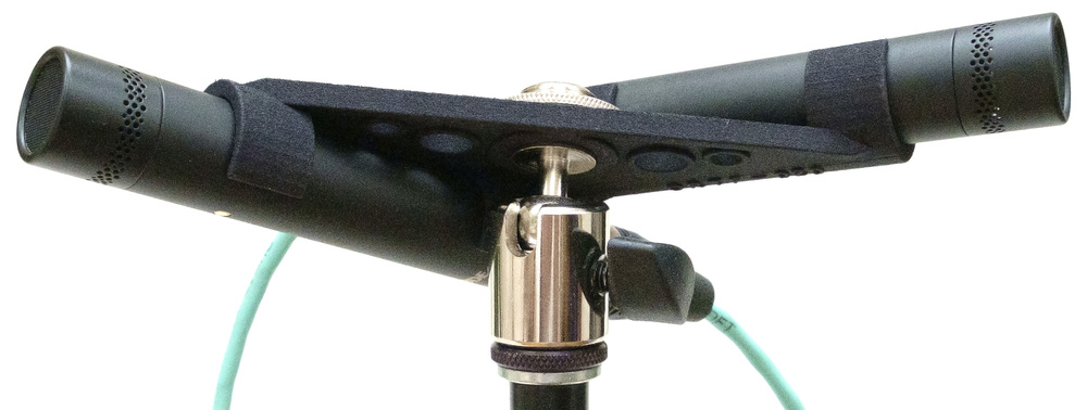
With an understanding of spaced and coincident stereo arrays, we can exploit the characteristics of both — using either established arrays, or by creating our own!
In previous parts of this series, we’ve explored the concepts of coincident and spaced stereo mic arrays. I hope you’ll recall that while coincident arrays generally deliver stable and precise stereo imaging, they’re often described as lacking ‘spaciousness’; in contrast, spaced arrays excel in the ‘spaciousness’ department but their stereo imaging is typically vague and unstable.
There’s no technical reason, though, why these disparate approaches can’t be combined to create a ‘hybrid’ array — one which uses directional polar patterns set with a mutual angle, but with the mics spaced apart. Indeed such stereo mic arrays are common and popular, and it’s probably fair to say that most recording engineers use them most of the time! As with all the other stereo arrays we’ve considered, there are no fixed rules; the recording engineer can employ any capsule spacing, polar pattern and mutual angle they think appropriate for any given situation, bearing in mind that these parameters interact to determine the Stereo Recording Angle (SRA) of the array, as well as the overall character of sound.
As with coincident mic array setups (crossed cardioids, Blumlein, Mid‑Sides and so forth), there are many precisely defined and named hybrid mic arrays, most being devised by European broadcasters in the early 1960s and consequently named after those organisations.
Popular Hybrid Stereo Arrays
The best known and most popular is the ORTF mic technique, which was developed around 1964 by the Office de Radiodiffusion Télévision Française (the post‑war French state broadcaster, which was broken up into seven new broadcasting companies in 1974, including TF1, TF2, FR3, and Radio France). For this array, two cardioid capsules are spaced apart by 170mm, and face outwards with a 110‑degree mutual angle to give an SRA of 96 degrees. At around the same time, in the Netherlands, the national broadcasting foundation (Nederlandse Omroep Stichting) came up with a variation on the same theme. This NOS configuration also uses cardioid capsules but they’re arranged with a 90‑degree mutual angle and a 300mm capsule spacing, a combination that gives a slightly narrower SRA of 81 degrees. And in Germany, the Deutsches Institut für Normung standards institute came up with the DIN array. This also employs cardioids with a mutual angle of 90 degrees, but its slightly narrower capsule spacing of 200mm gives a wider SRA of 102 degrees.
There are virtually limitless combinations of different capsule spacings, mutual angles and polar patterns, so not surprisingly there are other less well‑known named formats, such as RAI (cardioids, 210mm spacing, 100‑degree mutual angle) and EBS (cardioids, 250mm spacing, 90‑degree angle). I’ve skipped over these simply because they’re so similar to the arrays I’ve already described, but I will highlight one more option, since I plan on returning to it in the context of post‑production signal processing in a later article. The Gerzon array employs cardioid capsules with a mutual angle of 120 degrees and a spacing of just 50mm, giving an SRA of 130 degrees. This array was named after and promoted in the 1980s by Michael Gerzon, a genius who’s probably best known as the inventor of (first‑order) Ambisonics and the SoundField microphone, and who credited the array to award‑winning recording engineer and producer, Tony Faulkner. I wrote a detailed article about it five years ago, which you can read at www.soundonsound.com/techniques/gerzon-array.
To help you appreciate the practical differences between all these named arrays, Diagram 1 (below) indicates a notional orchestra on stage (the yellow block) with each hybrid stereo array positioned such that its SRA encompasses the full width of the orchestra. Since these arrays all use cardioid capsules, I’ve also included coincident X‑Y cardioids, with their nominal 196‑degree SRA.
Diagram 1: The tighter an array’s SRA, the further back you must placed it to have the source occupy the full stereo soundstage.
As can be seen, the NOS array’s relatively narrow 81‑degree SRA means it must be placed furthest from the orchestra, with the X‑Y coincident cardioids being the closest (typically right above the conductor). Consequently, each of these arrays will deliver a similar stereo width when auditioned on speakers, but very different perspectives (direct/reverb balance) due to their different distances from the stage; the more distant placements capture more ambience and reverberation than the closer ones, but also have different degrees of ‘spaciousness’ due to their differing capsule spacing. Again, NOS offers the greatest spaciousness and X‑Y the least.
Practical Mic Placement
But faced with so many options, how do you choose? As with coincident and spaced arrays, the basic principle of mic placement is to decide first on the desired perspective — how far away from the source(s) the mics should be for the optimum balance of direct to reverberant sound. When rigging and rehearsal time allows, you can assess that by listening to a single mic (of the type you intend to use for the stereo pair) facing directly forwards, with the monitoring switched to mono. Then adjust the placement (distance and height) to capture a sound with a nice overall balance of the ensemble on stage — but make it very slightly too dry, since it will sound more reverberant in stereo.
It can be very difficult to estimate the angle of the mics in a stereo array by eye, but a digital protractor makes precision quick and easy.
Having established the optimum position for the array, you can figure out the Stereo Recording Angle needed to encompass the entire ensemble. I’m not great at estimating angles by eye, so I use a digital protractor made by GemRed (I’m sure other brands make similar devices). I stand where the mic array is to be located, and open the protractor’s arms until they align with the outer edges of the wanted soundstage while looking over the hinge. The display in the protractor gives me the exact angle required, and I can then refer to a stereo mic visualiser app to explore the various combinations of mutual angle and capsule spacing for my chosen mics’ polar pattern that match that SRA value.
Choosing a smaller capsule spacing means more of the stereo information is conveyed as inter‑channel level differences, which means sharper imaging detail but less spaciousness. Selecting a wider capsule separation generates more inter‑channel time‑of‑arrival information, so a greater sense of spaciousness but less image stability and precision.
Changing the capsule spacing alters the SRA, of course, and that needs to be corrected by adjusting the mutual angle between the capsules. In doing so, a smaller mutual angle gives a more uniform tonality across the stereo image (the stage sources are less off‑axis). A larger mutual angle means far more of the wanted sound sources on stage will be being captured increasingly off‑axis, and so may have a less consistent tonality. This depends on the consistency of the mic’s polar pattern with frequency, and I’d generally avoid large mutual angles when using large‑diaphragm microphones for that reason, but when using good‑quality small‑diaphragm mics I find that it’s rarely a noticeable issue in practice.
Changing from cardioid to subcardioid has a similar effect to reducing the mutual angle — because a sound source must be further away from the centre to generate the same inter‑channel level difference.
A third variable, especially when using multi‑pattern mics, is to change the capsule polar patterns. For example, changing from cardioid to subcardioid has a similar effect to reducing the mutual angle — because a sound source must be further away from the centre to generate the same inter‑channel level difference. Swapping cardioid for hypercardioid is akin to increasing the mutual angle, and narrowing the SRA. This extra option means we can add a third rule:
- Rule 1: Reducing the Mutual Angle increases the Stereo Recording Angle.
- Rule 2: Reducing the Capsule Spacing increases the Stereo Recording Angle.
- Rule 3: Reducing the Pattern Directivity increases the Stereo Recording Angle.
Again, it’s important to remember that all of these parameters interact to some extent, so the ideal mic placement and array configuration is often arrived at iteratively. So my advice is to always allow yourself plenty of time to work through that process, auditioning the results at each step to make informed decisions and choices. Yes, the perspective and stereo imaging can be fudged somewhat in post‑production, but it’s always far better to get it right at source, which is also the only way to arrive at the best possible sound quality.
With experience, it becomes easier to intuit an appropriate array close to the ideal from the outset. But building that experience takes a lot of time, experimentation and critical assessment in many different recording situations and environments! Recording is a craft and an art — it takes time to hone these skills.
Next Time
In the next part of this series, I’ll discuss in more depth the practical considerations when choosing hybrid stereo arrays, examine the concept of ‘angular distortion’, and explore the potential of more sophisticated stereo arrays using more than two mics, including the famous Decca Tree.
Audio Examples
Thanks again to the Teme Valley South Churches Choir (TVSCC), who repeatedly performed ‘If Ye Love Me’ by Thomas Tallis to help us demonstrate the characteristics of various stereo mic arrays.
The media files associated with this series (https://sosm.ag/this-is-stereo-media) include an example of an ORTF hybrid mic array (track 8, ‘ORTF’). This was captured using a pair of Rode TF5 microphones supported on a 3D‑printed clip designed specifically for that purpose and mounted on the same stand that also accommodated the Mid‑Sides array (track 7, ‘Coincident Mid‑Sides’). The latter makes a useful comparator for coincident versus hybrid arrays — but remember to adjust the Mid‑Sides decoder to match the decoded stereo image width of the ORTF pair. Also mounted on the same stand was a pair of spaced omnidirectional mics (track 11, ‘OCCO Omnis’), with a capsule spacing of 690mm for an SRA of 96 degrees — exactly the same as the ORTF array. Consequently, these spaced omnis allow a direct comparison between a pure spaced array and the hybrid ORTF setup.
Listening to the differences between these three alternative arrays, in terms of stereo imaging, spaciousness and perspective can be very illuminating. Unfortunately, changes in tonality across the sound stage are almost impossible to perceive from these examples because of the relatively strong reverberation. But in drier acoustics, and with a wider sound source (for example, a full orchestra) those differences would be more apparent between the different arrays. Sadly, I didn’t have sufficient mics or recorder channels available to rig DIN, NOS and Gerzon hybrid arrays too, but hopefully this ORTF example will give a flavour of the benefits of hybrid arrays — and I would certainly encourage anyone interested in stereo recording to experiment with different configurations.
As mentioned, the ORTF, NOS and DIN arrays are very precisely specified. For example, if the capsules aren’t exactly 170mm apart and facing 55 degrees left and right, then it’s not an ORTF array. Rather, it’s a hybrid array of your own design. But if you find that 170mm spacing with a mutual angle of 120 degrees works nicely in a particular situation, there’s absolutely nothing wrong with using that combination. Just don’t call it an ORTF array!

