We conclude our primer on coincident arrays by exploring the theory and practice of Mid‑Sides miking.
In Part 3 we continued our exploration of coincident (X‑Y) stereo microphone arrays, and looked at how the Stereo Recording Angle (SRA) can be altered, either by changing the mutual angle between the two mics, or by changing the mic polar patterns. In this instalment, I’ll delve into another form of coincident mic array — the mysterious Mid‑Sides format — and discuss some tools that can help visualise and calculate the SRAs of different stereo arrays. As always, you can find the audio examples that accompany this series at https://sosm.ag/this-is-stereo-media
Mid‑Sides
The term Mid‑Sides seems to induce fear or confusion in many recordists and, because the explanations often use equations, some seem to think it will be hard work! But Mid‑Sides is really nothing more than the conventional left‑right (L‑R) stereo format viewed through a different lens, and in practice it’s very easy. L‑R and M‑S both carry exactly the same information, and are completely interchangeable through a simple ‘matrix’ process.
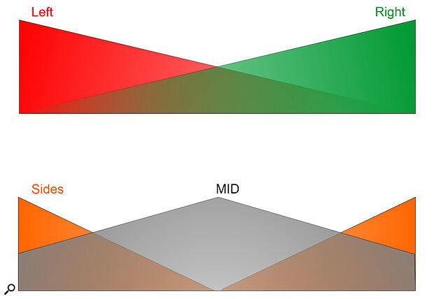
Diagram 1 illustrates how audio information is portrayed in each channel in both formats.
 Diagram 1: M‑S and L‑R are both stereo formats, and carry exactly the same stereo information, but different parts of the signal are conveyed on each of the two channels.
In the L‑R format (top), a fully‑left sound source is carried only in the left (red) channel. But as soon as it starts to move towards the right, some left‑channel information is also carried partly in the right (green) channel too. The further the source moves right, the stronger it gets in the right channel. A central sound source is carried equally in the left and right channels, of course.
For the Mid‑Sides format, the Mid channel carries everything, no matter where it is positioned in the stereo image. But a central sound is 6dB louder than if that sound was fully left or right, because the same signal exists in both channels (if you add two identical signals the result is 6dB louder). The Sides channel, as the name implies, is strongest for signals that exist only in one channel (whether left or right) at either side of the stereo image. The signal strength falls as the source moves towards the centre, and a central sound source is not carried in the Sides channel at all. And all of this behaviour is defined by two simple equations:
- Mid = Left + Right (the sum of both channels).
- Sides = Left — Right (the difference between channels).
Hopefully you can see that, since you’re adding the left and right, the Mid channel is exactly the same as a conventional mono sum. The Sides channel, on the other hand, essentially carries all the stereo‑width ‘goodness’ that you lose when summing to mono — the wider a sound source in the stereo image, the stronger it will be in the Sides channel. Importantly, exactly the same sum and difference matrix processing converts the other way, too:
- Left = Mid + Sides (sum)
- Right = Mid — Sides (difference)
Consequently, whatever format you feed into an M‑S matrix, the opposite format will appear at its output. L‑R becomes M‑S, and M‑S becomes L‑R; it’s the same process for both conversions. There’s a small but important caveat, though!
Imagine you want to convert L‑R to M‑S to adjust the stereo width, and then convert the narrowed/widened signal back to L‑R (this is precisely what most stereo‑width controls do in mixers). The first matrix outputs an M‑S signal that we route into another matrix that outputs L‑R. The stereo channels L and R that we start with become M (=L+R) and S (=L‑R). Those M‑S signals go into a second matrix to derive L and R again (L=M+S and R= M‑S). But look what happens if we substitute those M and S terms in the second matrix for the Left and Right terms that we started out with:
- Left output = M+S = (L+R)+(L‑R) = 2L
- Right output = M‑S = (L+R)‑(L‑R) = 2R
As you can see in the rightmost part of those two equations, we now have twice as much output signal level as we started with. Put another way, the output of the second matrix is 6dB louder than the original signal. Sometimes that won’t matter, as it’s not difficult to adjust the signal level manually, but usually we need to preserve unity gain and headroom throughout a signal chain. A simple solution is widely (but not universally) adopted: each matrix is designed with 3dB attenuation at both its outputs. That way, when two matrix processes are combined, the overall signal maintains unity gain. If you notice a slight (3dB) loss in level when passing a signal through a single matrix, this will be why!
The main advantage of the M‑S format is that varying the ratio of the Mid and Sides components adjusts the width of the stereo sound stage.
Practical Benefits Of Mid‑Sides
OK, enough of all the maths! What is M‑S actually useful for in practice? The main advantage of the M‑S format is that varying the ratio of the Mid and Sides components adjusts the width of the stereo sound stage. With no Sides signal you’re left with pure mono. And as the Sides level is increased, the stereo width increases with it. Full (100 percent) width is when the Mid and Sides signals are exactly equal in level, and pushing the Sides level higher still creates an ‘out‑of‑phase’ effect, whereby sounds appear to come from ‘outside’ the speakers, but do so in a very unstable (and, often, arguably unpleasant) way.
The Mid and Sides signals can also be processed independently too, and a very powerful technique is to boost and/or cut the level of the Sides signal using an equaliser. This allows the stereo width to be adjusted in a frequency‑selective way. For example, rolling off the low end in the Sides leaves all the bass in the Mid channel only, so it’s all in the centre of the stereo image — this is a standard process for cutting vinyl records. Alternatively, using a high‑shelf cut in the Sides channel narrows the stereo image slightly at high frequencies, and that’s exactly how EMI’s Stereosonic Shuffler works (Diagram 2), as mentioned last month in Part 3.
 Diagram 2: EMI’s Stereosonic Shuffler employs a high‑shelf cut in the Sides channel to narrow the stereo image slightly at high frequencies.
Mid‑Sides Stereo Array
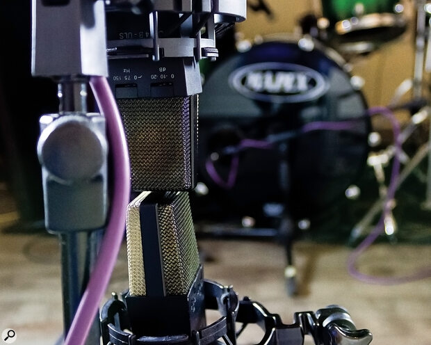
So far, I’ve discussed creating Mid‑Sides signals from left‑right stereo using a matrix process. But we can also capture M‑S stereo signals directly at source, using a pair of microphones — an idea that Alan Blumlein came up with almost a century ago. Like conventional L‑R stereo, two microphones are required, and they must be mounted coincidently, such that they capture only amplitude differences between the two channels (ie. with no time‑of‑arrival differences).
The Mid signal can be captured using any desired polar pattern that ‘hears’ all the sound sources consistently, and provides a suitable perspective (in terms of the direct sound:reverberation ratio)....
You are reading one of the locked Subscribers-only articles from our latest 5 issues.
You've read 30% of this article for FREE, so to continue reading...
- ✅ Log in - if you have a Digital Subscription you bought from SoundOnSound.com
- ⬇️ Buy & Download this Single Article in PDF format £0.83 GBP$1.49 USD
For less than the price of a coffee, buy now and immediately download to your computer, tablet or mobile. - ⬇️ ⬇️ ⬇️ Buy & Download the FULL ISSUE PDF
Our 'full SOS magazine' for smartphone/tablet/computer. More info... - 📲 Buy a DIGITAL subscription (or 📖 📲 Print + Digital sub)
Instantly unlock ALL Premium web articles! We often release online-only content.
Visit our ShopStore.

